Freescale Semiconductor DSP56366 User Manual
Page 23
DSP56366 24-Bit Digital Signal Processor User Manual, Rev. 4
Freescale Semiconductor
iii
•
The word “assert” means that a high true (active high) signal is pulled high to V
CC
or that a low
true (active low) signal is pulled low to ground. The word “deassert” means that a high true signal
is pulled low to ground or that a low true signal is pulled high to V
CC
.
•
Pins or signals that are asserted low (made active when pulled to ground)
— In text, have an overbar (e.g., RESET is asserted low).
— In code examples, have a tilde in front of their names. In example below, line 3 refers to the
SS0 pin (shown as ~SS0).
•
Sets of pins or signals are indicated by the first and last pins or signals in the set (e.g., HA1–HA8).
•
Code examples are displayed in a monospaced font, as shown below:
Example Sample Code Listing
BFSET
#$0007,X:PCC Configure:
line 1
; MISO0, MOSI0, SCK0 for SPI master
line 2
; ~SS0 as PC3 for GPIO
line 3
•
Hex values are indicated with a dollar sign ($) preceding the hex value, as follows: $FFFFFF is the
X memory address for the core interrupt priority register (IPR-C).
•
The word “reset” is used in four different contexts in this manual:
— the reset signal, written as “RESET,”
— the reset instruction, written as “RESET,”
— the reset operating state, written as “Reset,” and
— the reset function, written as “reset.”
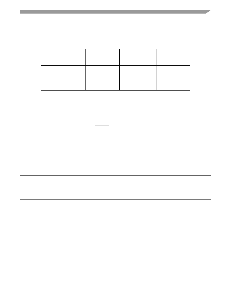
High True/Low True Signal Conventions
Signal/Symbol
Logic State
Signal State
Voltage
PIN
1
1
PIN is a generic term for any pin on the chip.
True
Asserted
Ground
2
2
Ground is an acceptable low voltage level. See the appropriate data sheet for the range of
acceptable low voltage levels (typically a TTL logic low).
PIN
False
Deasserted
V
CC
3
3
V
CC
is an acceptable high voltage level. See the appropriate data sheet for the range of acceptable
high voltage levels (typically a TTL logic high).
PIN
True
Asserted
V
CC
PIN
False
Deasserted
Ground