7 icr initialize bit (init) bit 7, 2 command vector register (cvr), 1 cvr host vector (hv[6:0]) bits 0-6 – Freescale Semiconductor DSP56366 User Manual
Page 117: Icr initialize bit (init) bit 7 -23, Command vector register (cvr) -23, Cvr host vector (hv[6:0]) bits 0–6 -23, Figure 6-13, Table 6-13, Init command effect -23
HDI08 – External Host Programmer’s Model
DSP56366 24-Bit Digital Signal Processor User Manual, Rev. 4
Freescale Semiconductor
6-23
from the host request rate – i.e., for every two or three host processor data transfers of one byte each, there
is only one 24-bit DSP CPU interrupt.
If either HDM1 or HDM0 in the HCR register are set, bits 6 and 5 become read-only bits that reflect the
value of HDM[1:0].
6.6.1.7
ICR Initialize Bit (INIT) Bit 7
The INIT bit is used by the host processor to force initialization of the HDI08 hardware. During
initialization, the HDI08 transmit and receive control bits are configured.
Using the INIT bit to initialize the HDI08 hardware may or may not be necessary, depending on the
software design of the interface.
The type of initialization done when the INIT bit is set depends on the state of TREQ and RREQ in the
HDI08. The INIT command, which is local to the HDI08, is designed to conveniently configure the HDI08
into the desired data transfer mode. The effect of the INIT command is described in
. When the
host sets the INIT bit, the HDI08 hardware executes the INIT command. The interface hardware clears the
INIT bit after the command has been executed.
6.6.2
Command Vector Register (CVR)
The CVR is used by the host processor to cause the DSP core to execute an interrupt. The host command
feature is independent of any of the data transfer mechanisms in the HDI08. It can be used to invoke
execution of any of the 128 possible interrupt routines in the DSP core.
6.6.2.1
CVR Host Vector (HV[6:0]) Bits 0–6
The seven HV bits select the host command interrupt address to be used by the host command interrupt
logic. When the host command interrupt is recognized by the DSP interrupt control logic, the address of
the interrupt routine taken is 2
∗ HV. The host can write HC and HV in the same write cycle.
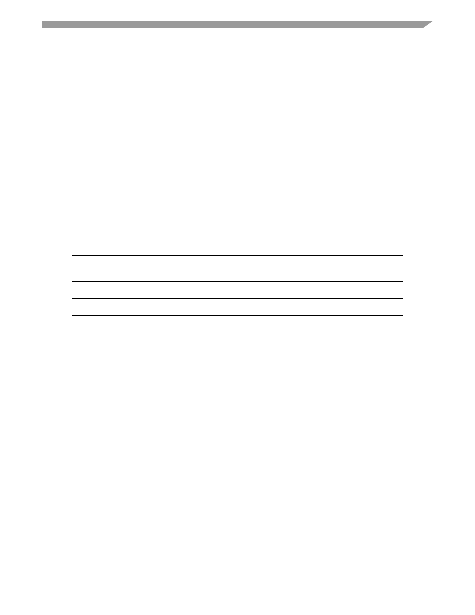
Table 6-13 INIT Command Effect
TREQ
RREQ
After INIT Execution
Transfer Direction
Initialized
0
0
INIT=0
None
0
1
INIT=0; RXDF=0; HTDE=1
DSP to Host
1
0
INIT=0; TXDE=1; HRDF=0
Host to DSP
1
1
INIT=0; RXDF=0; HTDE=1; TXDE=1; HRDF=0
Host to/from DSP
7
6
5
4
3
2
1
0
HC
HV6
HV5
HV4
HV3
HV2
HV1
HV0
Figure 6-13 Command Vector Register (CVR)