Figure 8-13, Esai data path programming model ([r/t]shfd=0) -38, Path programming model in – Freescale Semiconductor DSP56366 User Manual
Page 188: A) receive registers, B) transmit registers
ESAI Programming Model
DSP56366 24-Bit Digital Signal Processor User Manual, Rev. 4
8-38
Freescale Semiconductor
TSR disabled time slot period in network mode (as if data were being transmitted after the TSR was
written). When set, TODE indicates that data should be written to all the TX registers of the enabled
transmitters or to the time slot register (TSR). TODE is cleared when the DSP writes to all the transmit
data registers of the enabled transmitters, or when the DSP writes to the TSR to disable transmission of the
next time slot. If TIE is set, an ESAI transmit data interrupt request is issued when TODE is set. Hardware,
software, ESAI individual, and STOP reset clear TODE.
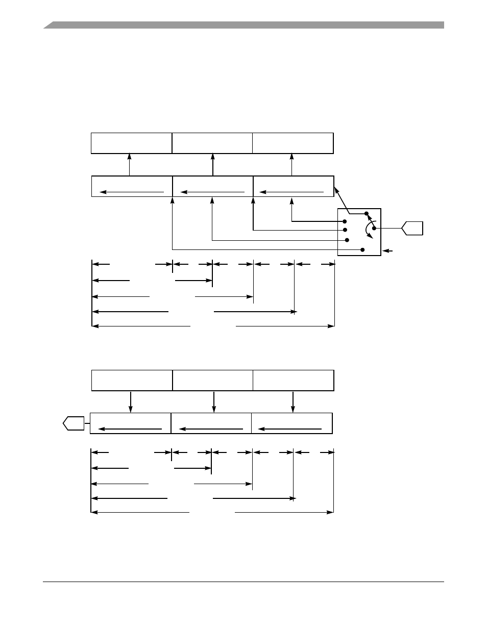
Figure 8-13 ESAI Data Path Programming Model ([R/T]SHFD=0)
SDI
23
16 15870
7
0
7070
RECEIVE HIGH BYTERECEIVE MIDDLE BYTERECEIVE LOW BYTE
ESAI RECEIVE DATA REGISTER
(READ ONLY)
SERIAL
RECEIVE
SHIFT
REGISTER
23
16 15870
7
0
7070
RECEIVE HIGH BYTERECEIVE MIDDLE BYTERECEIVE LOW BYTE
24 BIT
RSWS4-
RSWS0
NOTES:
1. Data is received MSB first if RSHFD=0.
2. 24-bit fractional format (ALC=0).
3. 32-bit mode is not shown.
16 BIT
12 BIT
8 BIT
(a) Receive Registers
SDO
23
16 15870
7
0
7070
TRANSMIT HIGH BYTETRANSMIT MIDDLE BYTETRANSMIT LOW BYTE
ESAI TRANSMIT DATA
REGISTER
(WRITE ONLY)
ESAI TRANSMIT
SHIFT REGISTER
23
16 15870
7
0
7070
TRANSMIT HIGH BYTETRANSMIT MIDDLE BYTETRANSMIT LOW BYTE
NOTES:
1. Data is sent MSB first if TSHFD=0.
2. 24-bit fractional format (ALC=0).
3. 32-bit mode is not shown.
4, Data word is left-aligned
(TWA=0,PADC=0).
(b) Transmit Registers
24-BIT DATA
0
0
16-BIT DATA
12-BIT DATA
8-BIT DATA
LSB
LSB
LSB
LSB
MSB
MSB
MSB
MSB
LEAST SIGNIFICANT
ZERO FILL
0
0
20-BIT DATA
LSB
MSB
20 BIT
24-BIT DATA
*
*
16-BIT DATA
12-BIT DATA
8-BIT DATA
LSB
LSB
LSB
LSB
MSB
MSB
MSB
MSB
* - LEAST SIGNIFICANT
BIT FILL
*
*
20-BIT DATA
LSB
MSB