Frf.8, Frf.8 -88 – Verilink 8100A (34-00237) Product Manual User Manual
Page 162

4-88
8 0 0 0 S e r i e s
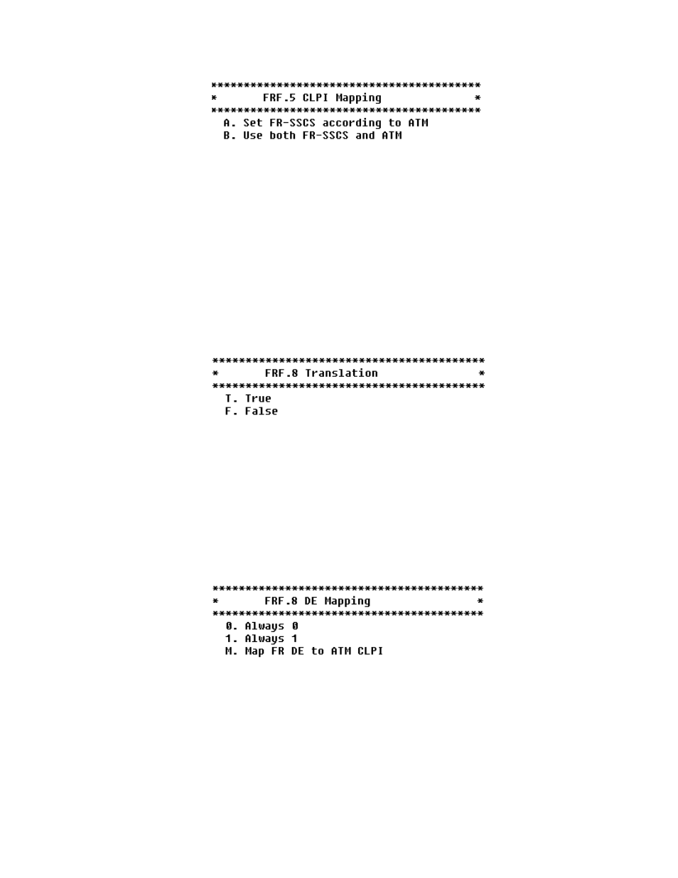
Figure 4.106
FRF.5 CLPI Mapping Menu
If you select “A”, no mapping is performed from the ATM layer to the Q.922
core layer. The FR-SSCS DE field is copied unchanged to the Q.922 core
frame DE field independent of CLP indication(s) received at the ATM layer.
If you select “B”, then if one or more ATM cells belonging to a frame has its
CLP field set to one or if the DE field of the FR-SSCS PDU is set to one, the
IAD will set the DE field of the Q.922 core frame.
FRF.8
If you select FRF8 from the Available Interworking Types menu (Figure
4.104), the menu below will be displayed.
Figure 4.107
FRF.8 Translation Menu
The selection of one of these options will determine how upper layer user
protocol encapsulation is handled. If you select “T”, the FRF.8 Interworking
function maps between the two encapsulations, translating between RFC 1490
and RFC 1483. If you select “F”, there is no translation of the data. It is
transported transparently between frame Relay DLCI and the ATM PVC. The
IAD forwards encapsulations unaltered; no mapping or fragmentation/
reassembly is performed on the data.
Select “T” to see the menu below displayed.
Figure 4.108
FRF.8 DE Mapping
If you select “0”, the discarding of cells will never be allowed, and if you
select “1”, discards will never be allowed.
If you select “M” (refer to the menu below), this allows bi-directional
mapping of the Frame Relay DE to the ATM CLPI. The purpose of this is to
identify in the protocol header that this frame may discard the frame if
congestion is indicated.
- 8108 Series IAD (34-00339.B) Product Manual 8508 Series IAD (34-00339.B) Product Manual 8208 Series IAD (34-00339.B) Product Manual 8308 Series IAD (34-00339.B) Product Manual 7500p Series IAD (34-00334.B) Product Manual 7200p Series IAD (34-00334.B) Product Manual 7000 Series (34-00334) Product Manual
