Frf.5, Frf.5 -87 – Verilink 8100A (34-00237) Product Manual User Manual
Page 161
C o n f i g u r a t i o n
4-87
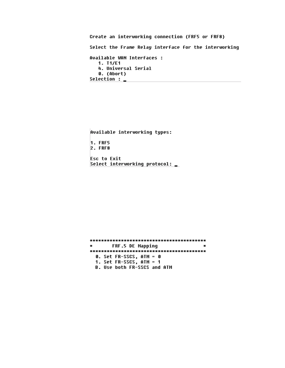
Figure 4.103
Interworking Connections Menu
After making your selection, select the desired port from the next menu. You
will then select the appropriate ATM interface from the available WAN
interfaces and once again will select the desired port. At this point, you will
select either FRF5 or FRF 8 Interworking protocol from the menu as shown
below.
Figure 4.104
Available Interworking Types Menu
When FRF.5 is selected, the ATM channel implements FRF.5 Network
Interworking, providing a Frame Relay link that can transport data for one or
more DLCIs. When FRF.8 is selected, the ATM channel implements FRF.8.1
Service Interworking, providing a conversion from a Frame Relay PVC to this
ATM PVC.
FRF.5
If you select FRF5, the menu below will be displayed.
Figure 4.105
FRF.5 DE Mapping Menu
If you select “0” or “1”, the DE field in the Q.922 core frame is copied
unchanged into the DE field in the FR-SSCS header and the ATM Cell Loss
Priority (CLP) of every ATM cell generated by the segmentation process of
that frame will be set to a constant value (either 0 or 1).
If you select “B” (refer to the menu below), the Discard Eligibility (DE) field
in the Q.922 core frame is copied unchanged into the DE field in the FR-
SSCS header and is mapped to the ATM Cell Loss Priority (CLP) of every
ATM cell generated by the segmentation process of that frame.
- 8108 Series IAD (34-00339.B) Product Manual 8508 Series IAD (34-00339.B) Product Manual 8208 Series IAD (34-00339.B) Product Manual 8308 Series IAD (34-00339.B) Product Manual 7500p Series IAD (34-00334.B) Product Manual 7200p Series IAD (34-00334.B) Product Manual 7000 Series (34-00334) Product Manual