Description of the demodulator, Overview, 7 description of the demodulator – Comtech EF Data SDM-300L3 User Manual
Page 30: 1 overview
SDM-300L3 Satellite Modem
Revision 1
Introduction
MN/SDM300L3.IOM
1–10
1.7
Description of the Demodulator
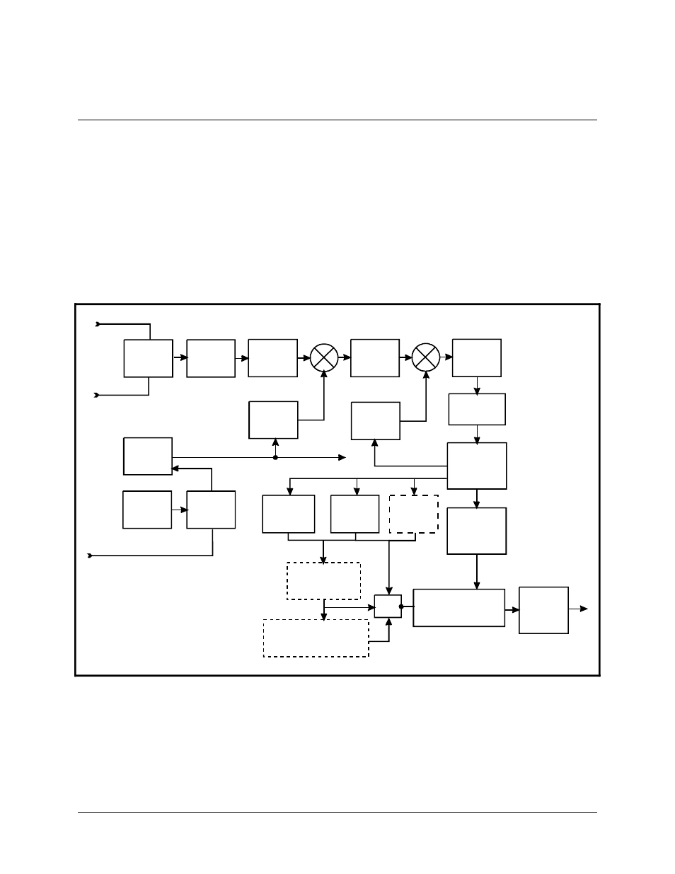
A block diagram of the demodulator is shown in Figure 1-2.
1.7.1
Overview
The demodulator converts PSK modulated carriers within the 950 to 1750 MHz range to
a demodulated baseband data stream. The converted modulation types are BPSK, QPSK,
OQPSK, and 8-PSK. The demodulator then performs FEC decoding on the data stream to
produce the error corrected data output to the data interface.
Figure 1-2
. Demodulator Block Diagram
DIGITAL
SIGNAL
PROCESSING
DIGITAL
CLOCK
RECOVERY-
LOOP
SWITCH
REF
VCXO
REF
PLL
OC XO
OPT
HIGH
STABILITY
AGC
LPF
BPF
LO #2
LOOPBACK
L-BAND INPUT
L-BAND INPUT
BPF
A TO D
CONVERTER
LO #1
REFERENCE
VITERBI
DECODER
SEQUENTIAL
DECODER
OPTIONAL
REED-SOLOMON
CODEC
DOPPLER/
PLESIOCHRONOUS
BUFFER
MUX
INTERFACE
OPTIONAL
OVERHEAD DEFRAMING
IBS/IDR, ASYNC/AUPC
DROP & INSERT
EXT REFERENCE
OPTIONAL
TURBO
CODEC
- CDD-880 (124 pages)
- CDM-800 (130 pages)
- ODMR-840 (184 pages)
- CDM-750 (302 pages)
- CDM-840 (244 pages)
- SLM-5650A (420 pages)
- CTOG-250 (236 pages)
- CDM-700 (256 pages)
- CDM-760 (416 pages)
- CDM-710G (246 pages)
- CDM-600/600L (278 pages)
- CDMR-570L (512 pages)
- CDM-625 (684 pages)
- CDM-625A (756 pages)
- CDD-564A (240 pages)
- CDD-564L (254 pages)
- CLO-10 (134 pages)
- MCED-100 (96 pages)
- CDMR-570AL (618 pages)
- CDM-600 LDPC (2 pages)
- BUC Power Supply Ground Cable (2 pages)
- MPP70 Hardware Kit for CDM-570L (4 pages)
- MPP50 Hardware Kit for CDM-570L (4 pages)
- CDM-625 DC-AC Conversion (4 pages)
- CDM-625 DC-AC Conversion with IP Packet Processor (4 pages)
- DMDVR20 LBST Rev 1.1 (117 pages)
- DMD2050E (212 pages)
- DMD-2050 (342 pages)
- DMD1050 (188 pages)
- OM20 (220 pages)
- QAM256 (87 pages)
- DD240XR Rev Е (121 pages)
- MM200 ASI Field (5 pages)
- DM240-DVB (196 pages)
- MM200 (192 pages)
- CRS-150 (78 pages)
- CRS-280L (64 pages)
- CRS-170A (172 pages)
- CRS-180 (136 pages)
- SMS-301 (124 pages)
- CiM-25/8000 (186 pages)
- CiM-25 (26 pages)
- CRS-500 (218 pages)
- CRS-311 (196 pages)
- CIC-20 LVDS to HSSI (26 pages)