D&i operation, 4 d&i operation – Comtech EF Data SDM-300L3 User Manual
Page 204
SDM-300L3 Satellite Modem
Revision 1
Modem Types
MN/SDM300L3.IOM
5–4
5.4 D&I
Operation
To operate the modem in the Drop & Insert configuration, the following cards must be installed
in the modem:
•
Overhead G.703/IDR/IBS/ASYNC/AUPC/D&I card
•
50-pin D relay adapter card
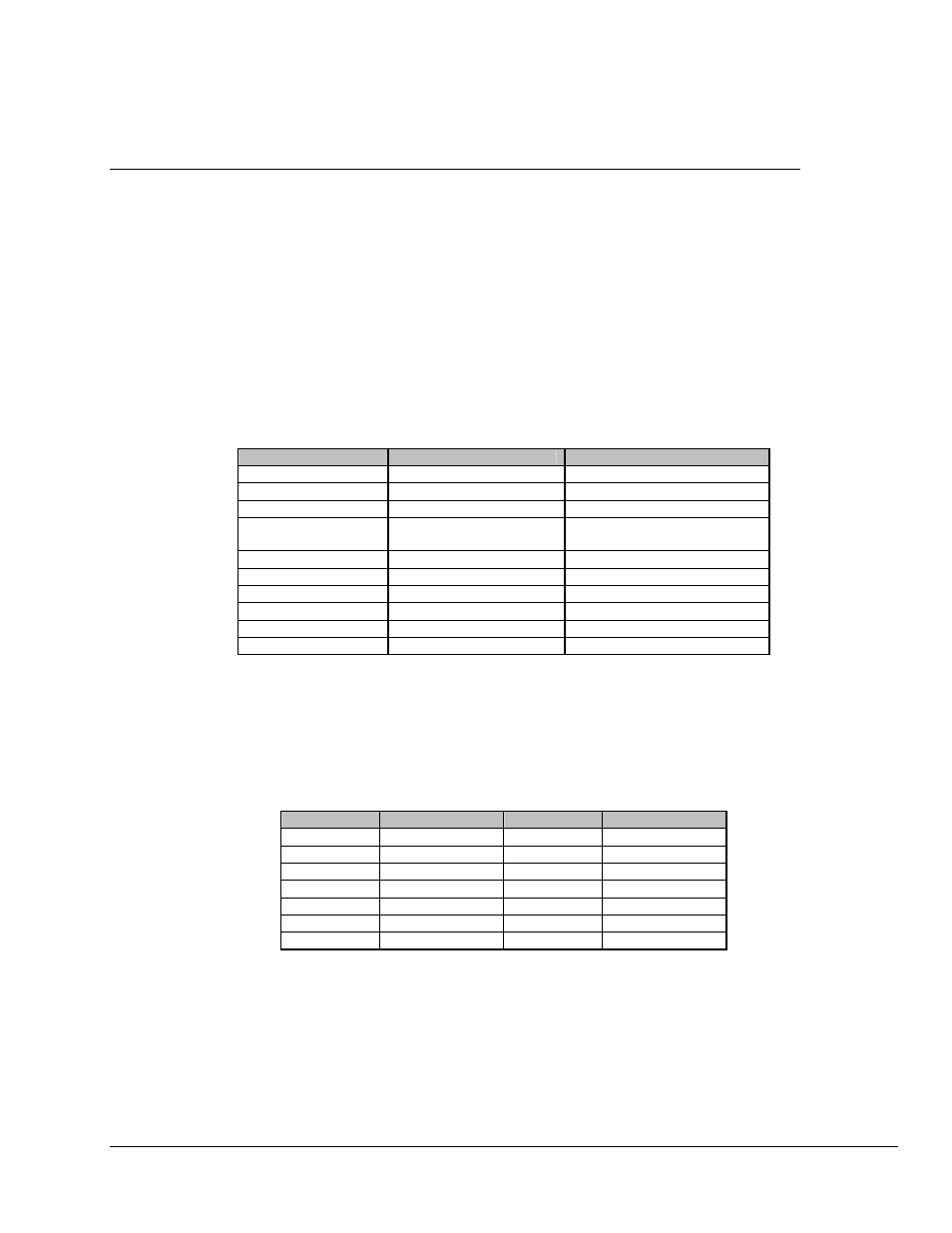
The D&I option is a FAST feature that must be enabled using the front panel and the Utility
Modem Type menu. Table A-5 lists the parameters that are accessible once the D&I modem type
is enabled.
T
ABLE
5-4. D&I
P
ARAMETER
S
ETTINGS
Parameter
Front Panel Settings
Reference Manual
Modem Type
D&I
Utility - Modem Type
TX Data/Code Rate
TX-V, QPSK 1/2 (NX64)
TX-IF Output
ON
Configuration - Demodulator
RX Data/Code Rate
RX-V, QPSK 1/2 (NX64)
Table 5-3
Configuration - Demodulator
TX Clock Source
TX Terrestrial
Configuration - Interface
Buffer Clock Source
Insert Clock
Configuration - Interface
TX Coding Format
HDB3
Configuration - Interface
RX Coding Format
HDB3
Configuration - Interface
Drop Format
E1CCS/E1CAS (E1)
Configuration - Interface
Insert Format
E1CCS/E1CAS (E1)
Configuration - Interface
In D&I operation, the transmit data rate is a fractional portion of the trunk T1 or E1 terrestrial
input. The N stands for the number of 64 kbps time slots available for transmission. Table A-6
shows the allowable TX data rates for D&I with the corresponding number of time slots available
for each data rate.
T
ABLE
5-5. N
X
64 C
HART
Time Slots
TX Data Rate
Time Slots
TX Data Rate
1
64 kbps
10
640 kbps
2
128 kbps
12
768 kbps
3
192 kbps
15
960 kbps
4
256 kbps
16
1024 kbps
5
320 kbps
20
1280 kbps
6
384 kbps
24
1536 kbps
8
512 kbps
30
1920 kbps