Comtech EF Data SDM-650B User Manual
Page 93
SDM-650B Satellite Modem
Configuration
Rev. 5
3–51
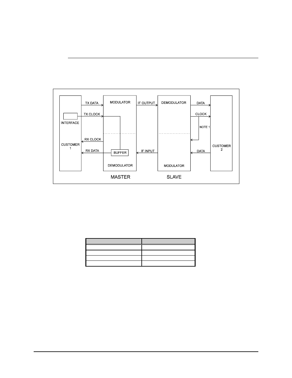
3.6.1.1 Master/Slave RS-422 or V.35
Refer to Figure 3-16 for the RS-422 or V.35 master/slave configuration.
Figure 3-16. RS-422 or V.35 Master Slave Configuration
Notes:
1. The clock may be looped back by using JP10 on the interface board.
2. Refer to Tables 3-1 or 3-2 for more information.
RS-422 Clock Loopback
V.35 Clock Loopback
Join RT-A to TT-A
Join SCR-A to SCTE-A
Join pin 8 to pin 17
Join pin V to pin U
Join RT-B to TT-B
Join SCR-B to SCTE-B
Join pin 26 to pin 35
Join pin X to pin Y
Note: By wiring the interface for clock turnaround, the impedance will be
reduced. This generally will cause no problem, providing the cable length to the
final terminal equipment is not excessive. Selecting “no loading” at the terminal
equipment will ensure correct line matching.
- CDD-880 (124 pages)
- CDM-800 (130 pages)
- ODMR-840 (184 pages)
- CDM-750 (302 pages)
- CDM-840 (244 pages)
- SLM-5650A (420 pages)
- CTOG-250 (236 pages)
- CDM-700 (256 pages)
- CDM-760 (416 pages)
- CDM-710G (246 pages)
- CDM-600/600L (278 pages)
- CDMR-570L (512 pages)
- CDM-625 (684 pages)
- CDM-625A (756 pages)
- CDD-564A (240 pages)
- CDD-564L (254 pages)
- CLO-10 (134 pages)
- MCED-100 (96 pages)
- CDMR-570AL (618 pages)
- CDM-600 LDPC (2 pages)
- BUC Power Supply Ground Cable (2 pages)
- MPP70 Hardware Kit for CDM-570L (4 pages)
- MPP50 Hardware Kit for CDM-570L (4 pages)
- CDM-625 DC-AC Conversion (4 pages)
- CDM-625 DC-AC Conversion with IP Packet Processor (4 pages)
- DMDVR20 LBST Rev 1.1 (117 pages)
- DMD2050E (212 pages)
- DMD-2050 (342 pages)
- DMD1050 (188 pages)
- OM20 (220 pages)
- QAM256 (87 pages)
- DD240XR Rev Е (121 pages)
- MM200 ASI Field (5 pages)
- DM240-DVB (196 pages)
- MM200 (192 pages)
- CRS-150 (78 pages)
- CRS-280L (64 pages)
- CRS-170A (172 pages)
- CRS-180 (136 pages)
- SMS-301 (124 pages)
- CiM-25/8000 (186 pages)
- CiM-25 (26 pages)
- CRS-500 (218 pages)
- CRS-311 (196 pages)
- CIC-20 LVDS to HSSI (26 pages)