Comtech EF Data SDM-650B User Manual
Page 28
Introduction
SDM-650B Satellite Modem
1–4
Rev. 5
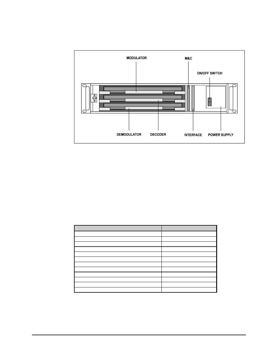
Figure 1-3. Modular Construction
Test points are located on the front board edge of the modulator, demodulator, and decoder
PCBs. Refer to Section 6.1.4 for listings and diagrams of the test points.
All controls and indicators for operation of the modem are located on the front panel. For
more information, refer to Chapter 4.
The chassis also contains the power supply; a fan is located on the rear panel.
The modem consists of the following assemblies:
Assembly
Drawing #
Chassis with Power Supply
AS/1099
PCB, M&C
AS/0356
PCB, Modulator
AS/0773-X
PCB, Demodulator
AS/0778-X
PCB, Sequential Decoder
AS/0365-X
PCB, Front Panel Control Board
AS/0361
PCB, Mother Board
AS/0979-1
PCB, Digital Interface V.35
AS/0627-2
(Optional)
PCB, Digital Interface DS1
AS/0569
(Optional)
PCB, Digital Interface MIL-STD-188-114 AS/0627-3
(Optional)
PCB, Doppler Buffer
AS/3812
(Optional)
PCB, Asynchronous Overhead Channel Unit
AS/1311-X
(Optional)
Note: X = various options available on the modulator, demodulator, and decoder
boards.