2 optional ext clk – Comtech EF Data SDM-650B User Manual
Page 68
Configuration
SDM-650B Satellite Modem
3–26
Rev.
5
They are available on the FAULT connector on the modem rear panel. Generation of
these fault conditions is described in Chapter 4.
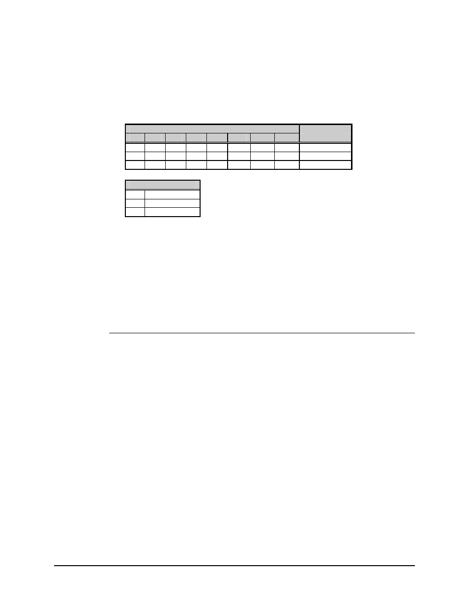
Table 3-4. G.703, 2048 kbit/s Interface Switch Configurations
SW1 Positions
Function
1
2
3
4
5
6
7
8
Selected
X X X X X X 0 0 AMI
CODE
X X X X X X 1 0 HDB3
0 0 0 0 0 1 X X 2048
kbit/s
Switch Positions
0 CLOSED
1 OPEN
X DON’T
CARE
Fault indicators are also provided on TTL open-collector drivers on the G.703 2048 kbit/s
connector.
• The TTL MOD fault indicates a Modulator fault or Common Equipment fault.
• The TTL DEMOD fault indicates a Demod or Common Equipment fault.
In order to facilitate testing of the modem when a G.703 signal is not available, the output
of the clock recovery circuitry is replaced by a 2.048 MHz clock whenever loss of the SD
signal is detected. This allows the modem to generate test signals at the proper data rate.
3.2.4.2 Optional EXT CLK
This option is used with the Doppler buffer.
The external clock can be used as an optional source of output clock for the optional
Doppler buffer. The two inputs, EXT CLK and /EXT CLK, are capacitively coupled to a
RS
−422 receiver and 470Ω resistors to ground. The EXT CLK is normally grounded by
jumper JP17, but may be removed to use RS-422.
In the normal mode, an unbalanced signal should be fed to EXT CLK. The signal may be
sine wave, square wave, or TTL. The signal should be at least 2 Vp-p and have a 40 to
60% duty cycle. Jumpers on the Doppler buffer should be set to select external clock
when this feature is used.