1 data i/o, 2 remote (j6), 3 fault (j7) – Comtech EF Data SDM-650B User Manual
Page 39
SDM-650B Satellite Modem
Installation
Rev. 5
2–3
2.2.1 DATA I/O
For information and pinouts on the data connectors, refer to Chapter 3.
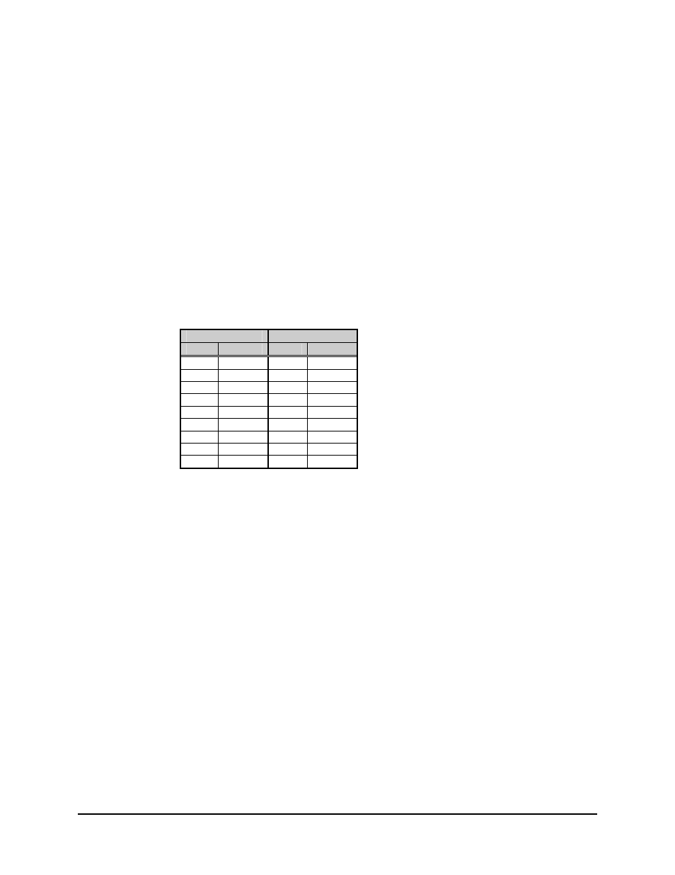
2.2.2 Remote (J6)
The remote connector on the modem is used to interface the Monitor and Control (M&C)
functions to a remote location. This interface can be either RS-232-C or RS-485. For a
complete discussion on the remote interface, refer to Chapter 3.
The remote interface is provided on a 9-pin female D connector. Screw locks are
provided for mechanical security of the mating connector. The remote connector is a Data
Circuit Terminating Equipment (DCE) interface.
RS-485
RS-232-C
Pin #
Name
Pin #
Name
1 GND 1
2 2
RD
(RX)
3 3
TD
(TX)
4 +RX/TX 4
5 -RX/TX 5 GND
6 6
DSR
7 7
RTS
8 +RX/TX 8 CTS
9 -RX/TX 9
2.2.3 Fault (J7)
The fault connector on the modem is used to provide FORM C contact closures for the
purpose of fault reporting.
There are three FORM C summary fault contacts:
• Modulator
• Demodulator
• Common
equipment
Refer to Chapter 4 for a complete discussion on monitored faults.
To obtain a system summary alarm, connect all FORM C contacts in parallel.