Comtech EF Data SDM-650B User Manual
Page 126
Theory of Operation
SDM-650B Satellite Modem
5–2
Rev.
6
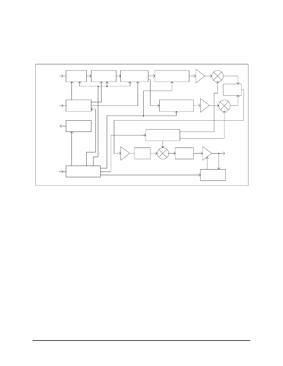
A block diagram of the modulator is shown in Figure 5-1.
INPUT
DATA
DATA
SCRAMBLER
DIFFERENTIAL
ENCODER
FORWARD ERROR
ENCODER
CORRECTION
I CHANNEL
NYQUIST FILTERS
COMBINER
POWER
NYQUIST FILTERS
Q CHANNEL
CLOCK
GENERATOR
CLOCK
OUTPUT
INPUT
CLOCK
CLOCK
SYNTHESIZER
IF
MULTIPLE LOOP
SYNTHESIZER
BANDPASS
IF OUTPUT
50 to 90 MHz
or
OUTPUT LEVEL
CONTROL
100 to 180 MHz
FILTER
FILTER
MICRO-COMPUTER
BUS INTERFACE
PROCESSOR
BUS
Figure 5-1. Modulator Block Diagram
Refer to Section 5.1.2 for a detailed description of the modulator.
See also other documents in the category Comtech EF Data Equipment:
- CDD-880 (124 pages)
- CDM-800 (130 pages)
- ODMR-840 (184 pages)
- CDM-750 (302 pages)
- CDM-840 (244 pages)
- SLM-5650A (420 pages)
- CTOG-250 (236 pages)
- CDM-700 (256 pages)
- CDM-760 (416 pages)
- CDM-710G (246 pages)
- CDM-600/600L (278 pages)
- CDMR-570L (512 pages)
- CDM-625 (684 pages)
- CDM-625A (756 pages)
- CDD-564A (240 pages)
- CDD-564L (254 pages)
- CLO-10 (134 pages)
- MCED-100 (96 pages)
- CDMR-570AL (618 pages)
- CDM-600 LDPC (2 pages)
- BUC Power Supply Ground Cable (2 pages)
- MPP70 Hardware Kit for CDM-570L (4 pages)
- MPP50 Hardware Kit for CDM-570L (4 pages)
- CDM-625 DC-AC Conversion (4 pages)
- CDM-625 DC-AC Conversion with IP Packet Processor (4 pages)
- DMDVR20 LBST Rev 1.1 (117 pages)
- DMD2050E (212 pages)
- DMD-2050 (342 pages)
- DMD1050 (188 pages)
- OM20 (220 pages)
- QAM256 (87 pages)
- DD240XR Rev Е (121 pages)
- MM200 ASI Field (5 pages)
- DM240-DVB (196 pages)
- MM200 (192 pages)
- CRS-150 (78 pages)
- CRS-280L (64 pages)
- CRS-170A (172 pages)
- CRS-180 (136 pages)
- SMS-301 (124 pages)
- CiM-25/8000 (186 pages)
- CiM-25 (26 pages)
- CRS-500 (218 pages)
- CRS-311 (196 pages)
- CIC-20 LVDS to HSSI (26 pages)