Comtech EF Data SDM-650B User Manual
Page 53
SDM-650B Satellite Modem
Configuration
Rev. 5
3–11
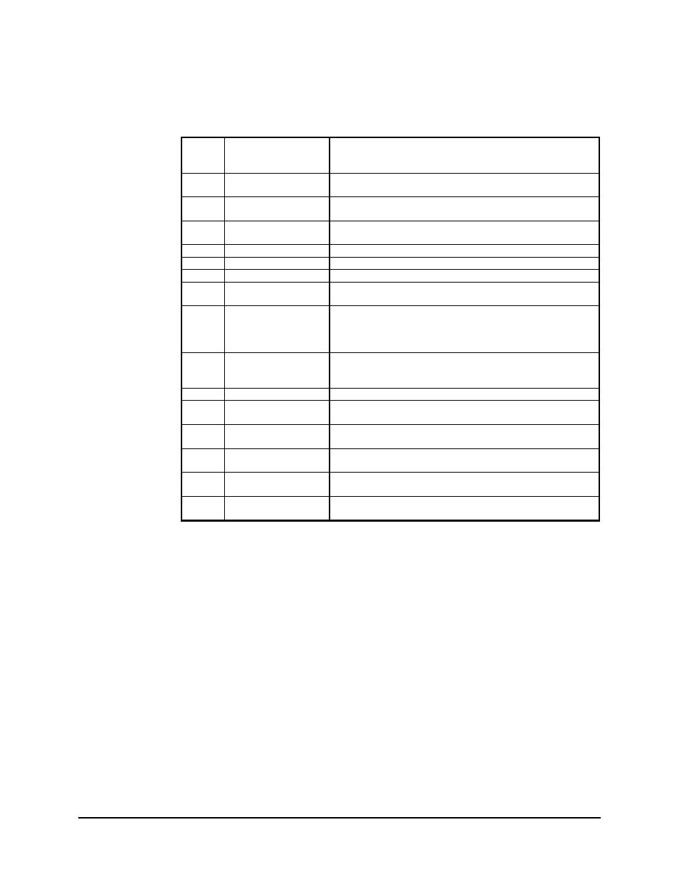
Table 3-1. AS/0627-3 Rev. E Board Jumper Selection
JP1
TX Clock Select
Normal
Invert
Auto
JP2
Interface Select
V.35 (-2)
MIL-STD-188/RS-232-C (-3)
(See Note Below)
JP3 RX
Data
Normal
(See Note Below)
Buffer
JP8 RX
Clock
Normal
(See Note Below)
Buffer
JP4 Address
Set
0
(See Note Below)
JP5 Address
Set
0
(See Note Below)
JP6 Address
Set
1
(See Note Below)
JP7 Address
Set
1
(See Note Below)
MIL (-3)
JP9
CTS to RTS
V.35 (Processor controller for
V.35 and RS-232-C)
MIL-STD-188/RS-422
(See Note Below)
(Hard loops CTS to RTS)
JP10 Loop
Timing
REM
ON
OFF
(See Note Below)
JP11
ASYNC Clk Syn (-5)
Cut Shorts
JP12
SCT
1 to 2 Invert
2 to 3 Normal
(See Note Below)
JP13
RD
1 to 2 Invert
2 to 3 Normal
(See Note Below)
JP14
RR
1 to 2 Invert
2 to 3 Normal
(See Note Below)
JP15
DM
1 to 2 Invert
2 to 3 Normal
(See Note Below)
JP16
SD
1 to 2 Invert
2 to 3 Normal
(See Note Below)
Note: Factory jumper settings for MIL-STD-188/RS-422 interface type.
These jumpers are factory set for each given configuration, and should not be changed.
This list is supplied for troubleshooting purposes only.