E.1 connector pinouts, E.2 installation instructions, E.2.1 parts required – Comtech EF Data SDM-650B User Manual
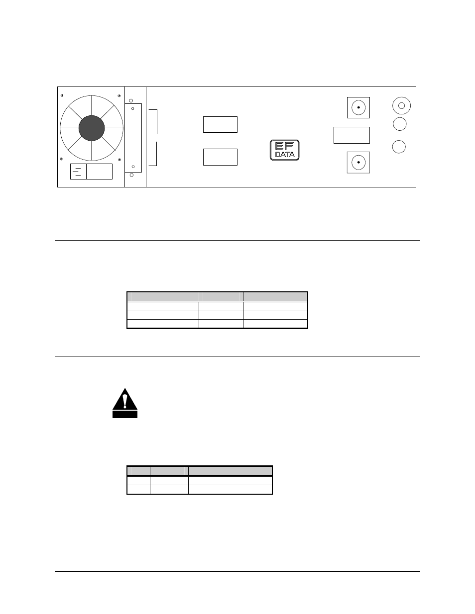
Page 254: Figure e-1. rear panel view
AGC Interface
SDM-650B Satellite Modem
E–2
Rev.
5
GROUND
ERDE
REMOTE
FAULT
J8
DATA
I/OI
J7
J6
CP1
CP2
TX/IF
OUTPUT
RX/IF
INPUT
MADE IN USA
J9
AGC
GAIN
OFFSET
J10
J11
Figure E-1. Rear Panel View
E.1 Connector Pinouts
The AGC interface is supplied on a 9-pin female D connector that is accessible from the
rear panel. Screw locks are provided for mechanical security of the mating connector.
Function
Name
Pin #
GROUND GND
9
AGC OUTPUT
AGC-OUT
1
NO CONNECTION
NC
2, 3, 4, 5, 6, 7, 8
E.2 Installation Instructions
CAUTION
Parts and assemblies may be damaged by Electrostatic Discharge (ESD).
ESD safety precautions should always be observed when handling parts.
E.2.1 Parts Required
Qty.
Part #
Description
1 PC/0769 AGC
Interface
1
FP/1873
Back Panel for the AGC
See also other documents in the category Comtech EF Data Equipment:
- CDD-880 (124 pages)
- CDM-800 (130 pages)
- ODMR-840 (184 pages)
- CDM-750 (302 pages)
- CDM-840 (244 pages)
- SLM-5650A (420 pages)
- CTOG-250 (236 pages)
- CDM-700 (256 pages)
- CDM-760 (416 pages)
- CDM-710G (246 pages)
- CDM-600/600L (278 pages)
- CDMR-570L (512 pages)
- CDM-625 (684 pages)
- CDM-625A (756 pages)
- CDD-564A (240 pages)
- CDD-564L (254 pages)
- CLO-10 (134 pages)
- MCED-100 (96 pages)
- CDMR-570AL (618 pages)
- CDM-600 LDPC (2 pages)
- BUC Power Supply Ground Cable (2 pages)
- MPP70 Hardware Kit for CDM-570L (4 pages)
- MPP50 Hardware Kit for CDM-570L (4 pages)
- CDM-625 DC-AC Conversion (4 pages)
- CDM-625 DC-AC Conversion with IP Packet Processor (4 pages)
- DMDVR20 LBST Rev 1.1 (117 pages)
- DMD2050E (212 pages)
- DMD-2050 (342 pages)
- DMD1050 (188 pages)
- OM20 (220 pages)
- QAM256 (87 pages)
- DD240XR Rev Е (121 pages)
- MM200 ASI Field (5 pages)
- DM240-DVB (196 pages)
- MM200 (192 pages)
- CRS-150 (78 pages)
- CRS-280L (64 pages)
- CRS-170A (172 pages)
- CRS-180 (136 pages)
- SMS-301 (124 pages)
- CiM-25/8000 (186 pages)
- CiM-25 (26 pages)
- CRS-500 (218 pages)
- CRS-311 (196 pages)
- CIC-20 LVDS to HSSI (26 pages)