1 specifications, 2 theory of operation – Comtech EF Data SDM-650B User Manual
Page 141
SDM-650B Satellite Modem
Theory of Operation
Rev. 6
5–17
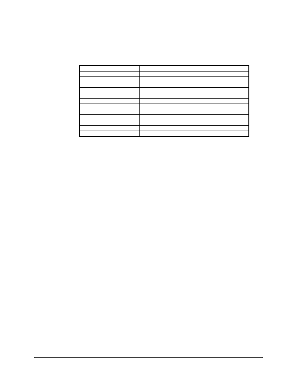
5.3.1 Specifications
Demodulation Type
QPSK (BPSK optional)
Frequency Range
50 to 90 MHz, or 100 to 180 MHz
Frequency Select Method
Synthesized
Frequency Step Size
2.5 kHz
Channel Spacing
0.7 times the data rate divided by the encoding rate
Input Level Desired Carrier
-55 to -30 dBm
Input Overload
0 dBm max
Input Impedance
75
Ω
(50
Ω
optional)
Input Return Loss
20 dB minimum
Filtering
Nyquist, 8 pole, 1 of 4 selectable
Image Rejection
40 dB minimum
Symbol Rate Range
9.1 to 3152 Ks/s
I/O Connector
DIN, 96-pin
5.3.2 Theory of Operation
A Costas Loop on the decoder board is used for carrier recovery.
The demodulator board provides only the I and Q channel signals, and has a VCXO
input.
The incoming modulated carrier enters the demodulator in the AGC amplifier, where the
carrier is filtered and amplified. The AGC circuit, controlled from off-card, provides
variable gain to maintain the signal level into the IF converter at a constant level over the
entire input dynamic range.
The carrier signal is converted to the fixed IF by the frequency synthesizer. The
synthesizer is programmable externally, to allow for acquisitions of carriers in the 50 to
90 MHz, or 100 to 180 MHz range.
The IF is split into two channels in the quadrature demodulator. Using an in-phase and a
quadrature carrier from a VCXO controlled externally, the quadrature demodulator
produces the I and Q channel baseband signals.
The I and Q channel baseband signals are amplified and filtered in the Nyquist filters.
These filters are matched filters to those of the transmitter, resulting in optimal detection
of the transmitted data. In addition, they effectively remove adjacent channels which
could corrupt the detection process.
The signal is amplified to the final level in the baseband amplifier. At this point, the
signal looks like the classic “eye” pattern. The signal is then quantized in the soft
decision interface and output to the card I/O connector.