3 demodulator, Figure 5-7. demodulator block diagram – Comtech EF Data SDM-650B User Manual
Page 140
Theory of Operation
SDM-650B Satellite Modem
5–16
Rev.
6
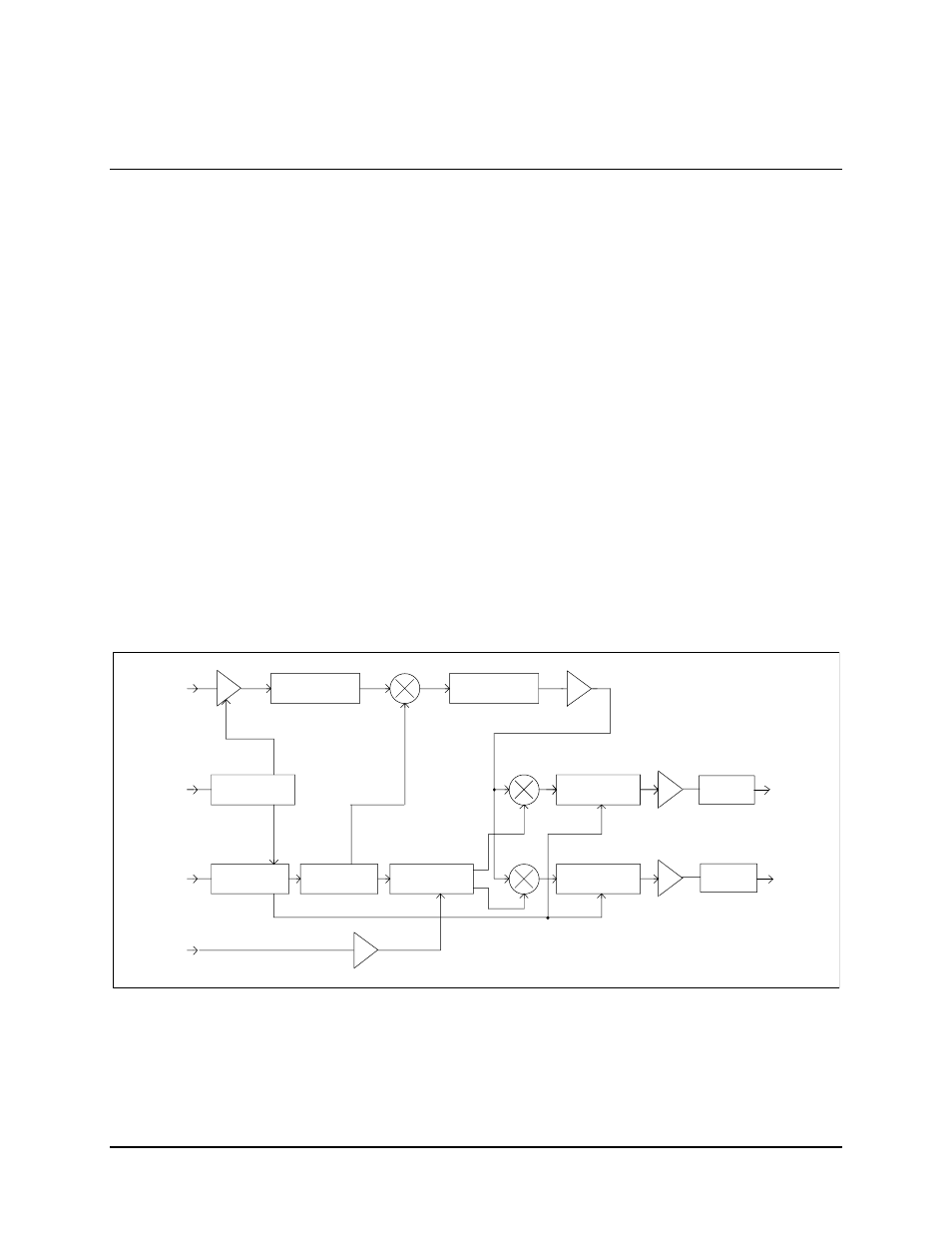
5.3 Demodulator
The modem demodulator card is a 10.25” x 14” card that fits in the lower-left slot of the
modem chassis.
The demodulator’s function is to accept a desired QPSK or BPSK modulated signal in the
50 to 90 MHz, or 100 to 180 MHz range. The card converts the signal to filtered
baseband in-phase and quadrature signals, which are then quantized and output from the
card.
Several subsections make up the card:
• AGC
amplifier
• Quadrature
demodulator
• IF
synthesizer
• Nyquist
filter
• Baseband
amplifier
• Soft decision interface
Refer to Figure 5-7 for a block diagram of the demodulator. Refer to Section 5.3.2 for a
detailed description of the subsections.
IF FILTER
LOWPASS FILTER
IF INPUT
50-90 MHZ
OR
100-180 MHZ
PROCESSOR
AGC INPUT
MICRO-COMPUTER
AGC CONTROLER
MULTIPLE LOOP
QUADRATURE
VCXO
I CHANNEL
NYQUIST FILTERS
Q CHANNEL
NYQUIST FILTERS
SYNTHESIZER
BUS INTERFACE
VCXO CONTROL
BUS
QUANTIZER
QUANTIZER
I CHANNEL
Q CHANNEL
Figure 5-7. Demodulator Block Diagram