3 test points, 1 modulator – Comtech EF Data SDM-650B User Manual
Page 152
Maintenance
SDM-650B Satellite Modem
6–8
Rev.
6
6.1.3 Test Points
The following sections detail front panel test points, with a description of the signal that
is to be present under normal operation.
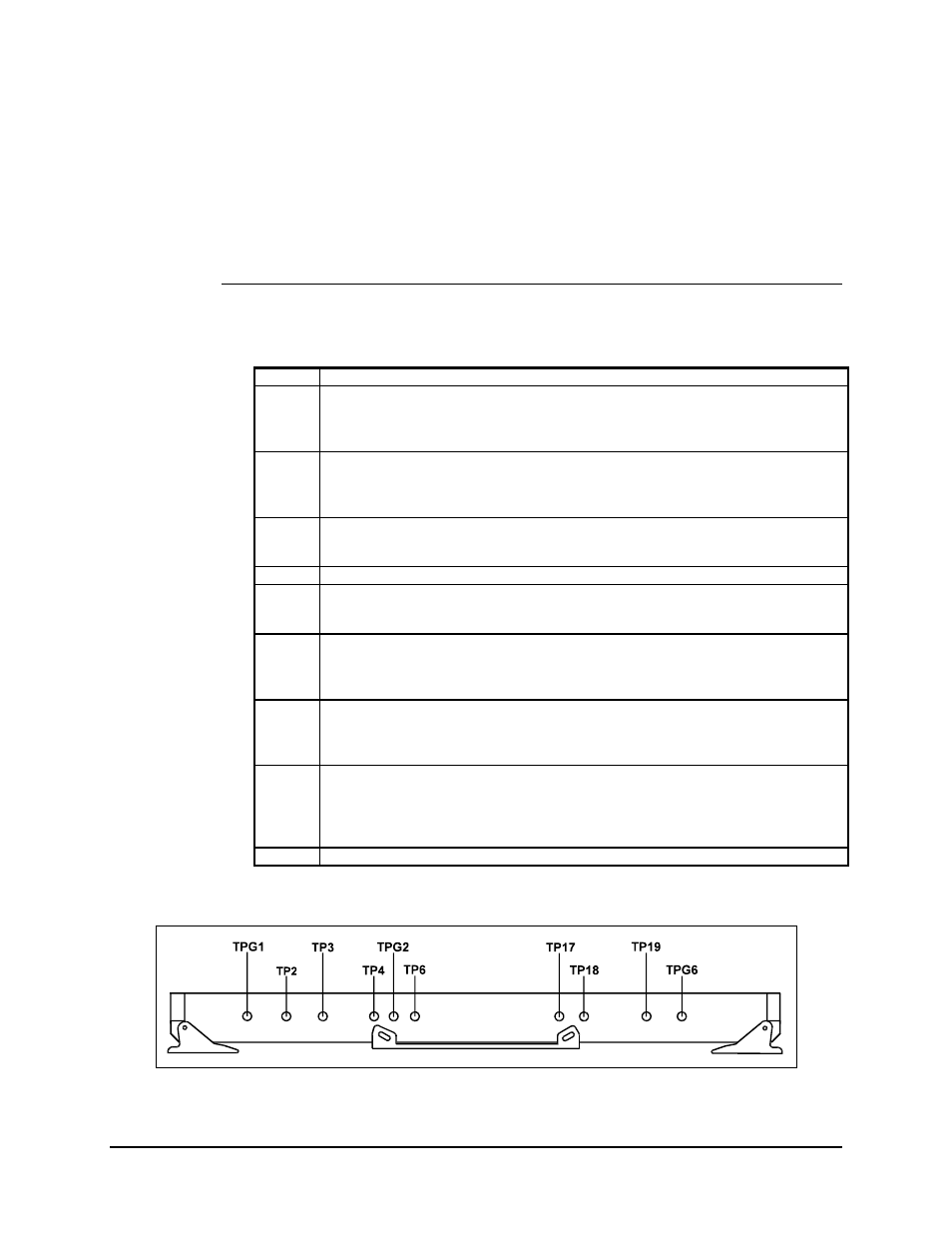
6.1.3.1 Modulator
Refer to Figure 6-7.
TPG1 Ground.
TP2
Q EYE Pattern.
Level is 2 Vp-p. The DC offset is 0V. This signal is the Q input to the QPSK
modulator. The eye pattern at this point is not equalized.
TP3
I EYE Pattern.
Level is 2 Vp-p. The DC offset is 0V. This signal is the I input to the QPSK modulator.
The eye pattern at this point is not equalized.
TP4
Q — Analog Data Eye Pattern.
Approximately 1.4 Vp-p between eye sample points.
TPG2 Ground.
TP6
I — Analog Data Eye Pattern.
Approximately 1.4 Vp-p between eye sample points.
TP17
I Channel Data.
TL level data that is output from the last register in the digital filter. The I channel
activity fault is monitoring the line.
TP18
Q Channel Data.
TTL level data that is output from the last register in the digital filter. The Q channel
activity fault is monitoring the line.
TP19
Symbol Rate Clock.
TTL level clock that is locked to the incoming data to the interface card. This clock is
at the symbol frequency and not at the data rate. The frequency is equal to: QPSK-
(DATA RATE/CODE RATE)/2 BPSK-(DATA RATE/CODE RATE).
TPG6 Ground.
Figure 6-7. Modulator Test Points