2 external connections – Comtech EF Data SDM-650B User Manual
Page 38
Installation
SDM-650B Satellite Modem
2–2
Rev.
5
4. Save the packing material for storage or reshipment purposes.
5. Inspect the equipment for any possible damage incurred during shipment.
6. Check the equipment against the packing list to ensure the shipment is complete.
7. Refer to Section 2.4 for further system installation instructions.
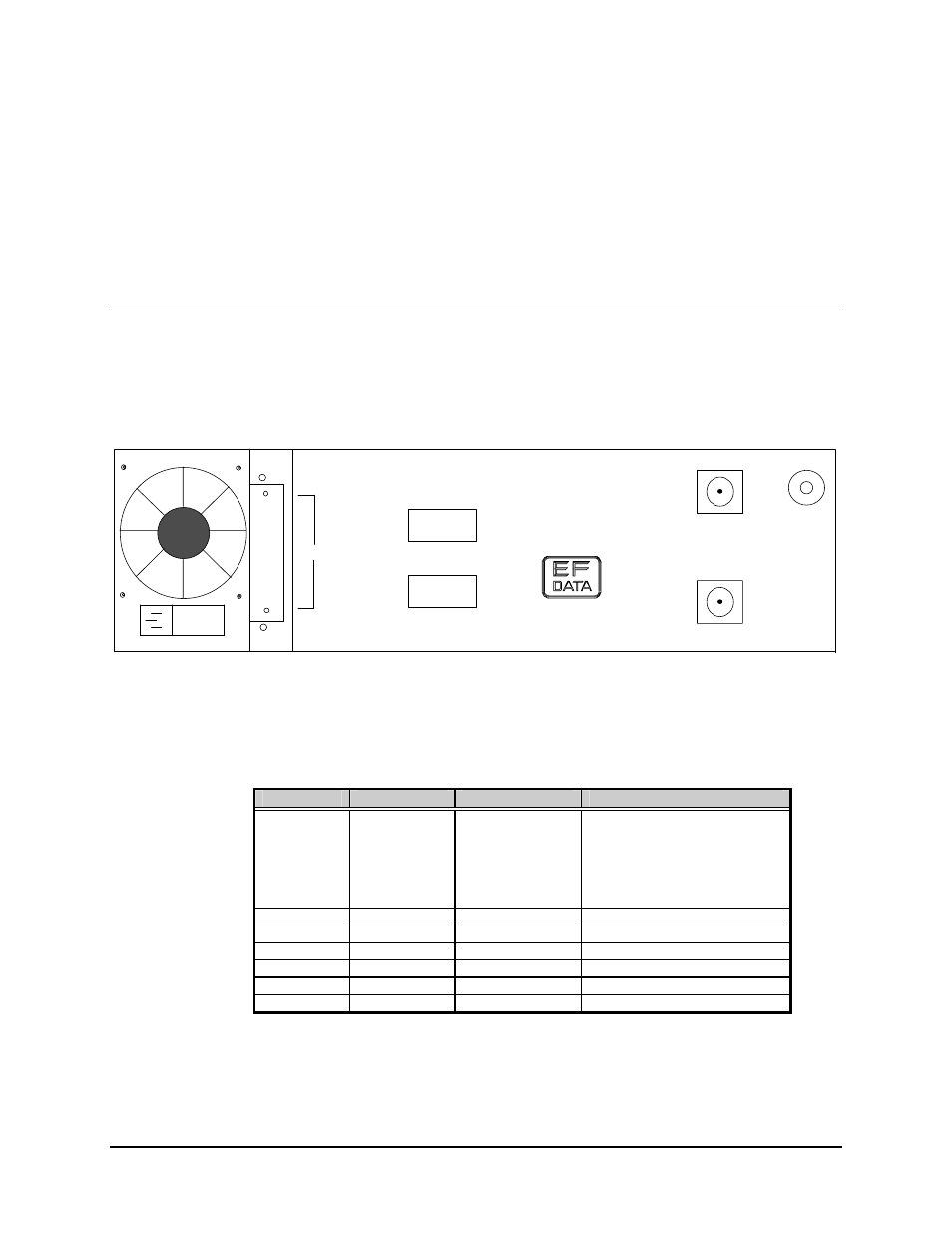
2.2 External Connections
Connections between the modem and other equipment are made through six connectors.
These connectors are listed in Table 2-1 and their locations are shown in Figure 2-1.
GROUND
ERDE
REMOTE
FAULT
J8
DATA
I/OI
J7
J6
CP1
CP2
TX/IF
OUTPUT
RX/IF
INPUT
MADE IN USA
Figure 2-1. SDM-650B Rear Panel View
Table 2-1. Rear Panel Connectors
Name
Ref. Design.
Connector Type
Function
DATA I/O
J8
Various
RS-422/MIL-STD-188 I/O
V.35 DATA I/O
DS1 DATA I/O
G.703 DATA I/O
Asynchronous Overhead
Channel Unit
REMOTE J6
9-Pin
D
Interface
FAULT
J7
9-Pin D
FORM C Fault Relay Contacts
IF OUTPUT
CP1
BNC
TX IF Output
IF INPUT
CP2
BNC
RX IF Input
AC POWER
None
Standard
AC Power Input
GROUND
GROUND
#10-32 Stud
Chassis Ground
The use of each connector is described in the following paragraphs.