4 connector pinouts – Comtech EF Data SDM-650B User Manual
Page 69
SDM-650B Satellite Modem
Configuration
Rev. 5
3–27
3.2.4.3 Switch Configuration for G.703 2048 kbit/s Interface
Switch 1 is an 8-position dip switch located at the end of the G.703 interface board.
Table 3-4 lists the switch settings for data rates and available coding for the G.703
2048 kbit/s interface.
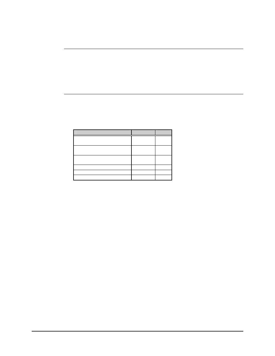
3.2.4.4 Connector Pinouts
The G.703 2048 kbit/s interface is provided on a 15-pin female D connector accessible
from the rear panel of the modem. Screw locks are provided for mechanical security of
the mating connector.
Signal Function
Name
Pin #
SEND DATA
SD-A
SD-B
1
9
RECEIVE DATA
RD-A
RD-B
3
11
MASTER CLOCK
MC-A
MC-B
7
8
MODULATOR FAULT
----
14
DEMODULATOR FAULT
----
15
GROUND GND
2,
4
See also other documents in the category Comtech EF Data Equipment:
- CDD-880 (124 pages)
- CDM-800 (130 pages)
- ODMR-840 (184 pages)
- CDM-750 (302 pages)
- CDM-840 (244 pages)
- SLM-5650A (420 pages)
- CTOG-250 (236 pages)
- CDM-700 (256 pages)
- CDM-760 (416 pages)
- CDM-710G (246 pages)
- CDM-600/600L (278 pages)
- CDMR-570L (512 pages)
- CDM-625 (684 pages)
- CDM-625A (756 pages)
- CDD-564A (240 pages)
- CDD-564L (254 pages)
- CLO-10 (134 pages)
- MCED-100 (96 pages)
- CDMR-570AL (618 pages)
- CDM-600 LDPC (2 pages)
- BUC Power Supply Ground Cable (2 pages)
- MPP70 Hardware Kit for CDM-570L (4 pages)
- MPP50 Hardware Kit for CDM-570L (4 pages)
- CDM-625 DC-AC Conversion (4 pages)
- CDM-625 DC-AC Conversion with IP Packet Processor (4 pages)
- DMDVR20 LBST Rev 1.1 (117 pages)
- DMD2050E (212 pages)
- DMD-2050 (342 pages)
- DMD1050 (188 pages)
- OM20 (220 pages)
- QAM256 (87 pages)
- DD240XR Rev Е (121 pages)
- MM200 ASI Field (5 pages)
- DM240-DVB (196 pages)
- MM200 (192 pages)
- CRS-150 (78 pages)
- CRS-280L (64 pages)
- CRS-170A (172 pages)
- CRS-180 (136 pages)
- SMS-301 (124 pages)
- CiM-25/8000 (186 pages)
- CiM-25 (26 pages)
- CRS-500 (218 pages)
- CRS-311 (196 pages)
- CIC-20 LVDS to HSSI (26 pages)