Comtech EF Data SDM-650B User Manual
Page 57
SDM-650B Satellite Modem
Configuration
Rev. 5
3–15
INT/EXT CLOCK
TO CONTROL LOGIC
LOOP TIMING
TO LOGIC CONTROL
TO BUFFER
OPTIONS
SCT
M
O
D
E
M
TX CLOCK
TX DATA
AUTO
CLOCK
SELECT
TO CONTROL LOGIC
LOOPBACK
T
E
R
R
E
S
T
R
I
A
L
TT
RT
SD
RD
ST
MC
EXTERNAL BUFFER CLOCK
INVERT
NORM
TO BUFFER
OPTIONS
RX CLOCK
RX DATA
COMMON EQUIPMENT
MODULATOR
DEMODULATOR
FAULT
RELAYS
CONTROL
LOGIC
RTS TO CTS JUMPER
TTL MODULATOR FAULT
SPARE (RS-232 ONLY)
RS
CS
TTL DEMODULATOR FAULT
DATA BUS TO M & C
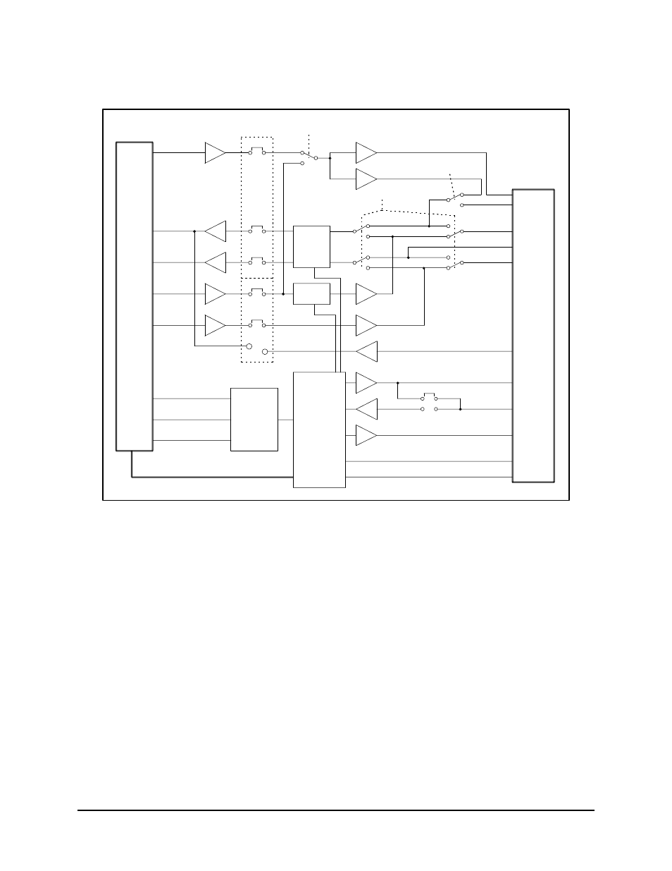
Figure 3-5. V.35 Interface Block Diagram
In either case, the phase relationship between the clock and data is not important as long
as the relationship meets the jitter specification. This is because a clock phase correction
circuit is provided, which shifts the clock away from the data transition times.
The clock selection is jumper-selectable at JP1 on the front edge of the board.
• When there is no jitter on the clock source, the Auto setting is used.
• The Normal setting is used when standard specifications on clock and data
relationships exist.
• The Invert mode is used when the incoming clock is inverted from the standard
clock and data relationship.