Comtech EF Data SDM-650B User Manual
Page 59
SDM-650B Satellite Modem
Configuration
Rev. 5
3–17
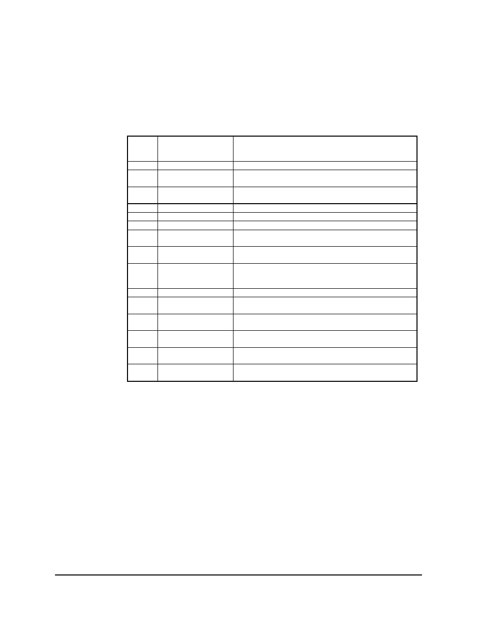
Table 3-2 lists the jumper settings for the V.35 interface. These jumpers are factory set
for a specific configuration. Clock selections, signal selections, and loop timing can be
changed upon individual needs.
Table 3-2. AS/0627-2 Rev. E Board Jumper Selection
JP1
TX Clock Select
Normal
Invert
Auto
(See Note Below)
JP2
Interface Select
V.35 (-2)
(See Note Below)
JP3 RX
Data
Normal
(See Note Below)
Buffer
JP8 RX
Clock
Normal
(See Note Below)
Buffer
JP4 Address
Set
1
(See Note Below)
JP5 Address
Set
0
(See Note Below)
JP6 Address
Set
1
(See Note Below)
JP7 Address
Set
1
(See Note Below)
V.35 (-2)
JP9
CTS to RTS
V.35
(See Note Below)
(Processor controller for V.35 and RS-232-C)
JP10 Loop
Timing
Auto
ON
OFF
(See Note Below)
JP11
ASYNC Clk Syn (-5)
Cut Shorts
JP12
SCT
1 to 2 Invert
2 to 3 Normal
(See Note Below)
JP13
RD
1 to 2 Invert
2 to 3 Normal
(See Note Below)
JP14
RR
1 to 2 Invert
2 to 3 Normal
(See Note Below)
JP15
DM
1 to 2 Invert
2 to 3 Normal
(See Note Below)
JP16
SD
1 to 2 Invert
2 to 3 Normal
(See Note Below)
Note: Factory jumper settings for V.35 interface type.