3 sequential decoder/demod card – Comtech EF Data SDM-650B User Manual
Page 154
Maintenance
SDM-650B Satellite Modem
6–10
Rev.
6
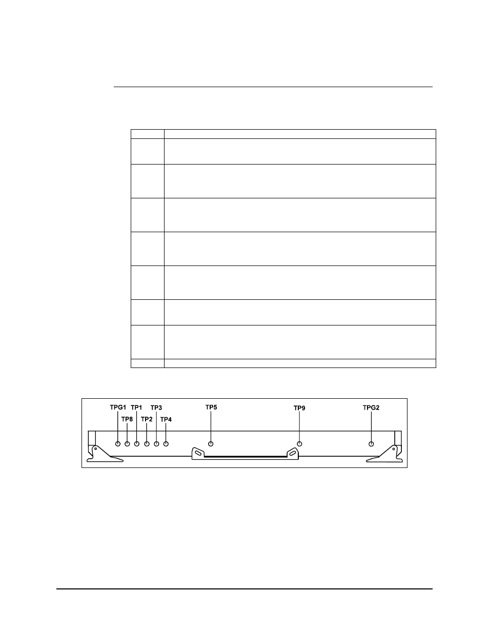
6.1.3.3 Sequential Decoder/Demod Card
Refer to Figure 6-9.
TPG1 Ground.
TP8
VCXO Control Voltage.
Sweeps from -2.5V to +2.5 VDC.
TP1
IMAG — I Channel Magnitude Bit.
Result of the soft bits from the soft decision interface. Transitions will occur in the
presence of noise in the RF signal.
TP2
QSGN — Q Channel Sign Bit.
Result of the hard bits from the soft decision interface. 50% duty cycle random data
is displayed.
TP3
ISGN — I Channel Sign Bit.
Result of the hard bits from the soft decision interface. 50% duty cycle random data
is displayed.
TP4
QMAG — Q Channel Magnitude Bit.
Result of the soft bits from the soft decision interface. Transitions will occur in the
presence of noise in the RF signal.
TP5 SYMBOL
CLOCK.
Result of the data clock recovery loop in the demod processor section.
TP9 DECODER
LOCK.
TTL levels. TTL high indicates a locked condition. A TTL low indicates an unlocked
condition.
TPG2 Ground.
Figure 6-9. Sequential Decoder/Demod Card Test Points