Comtech EF Data SDM-650B User Manual
Page 64
Configuration
SDM-650B Satellite Modem
3–22
Rev.
5
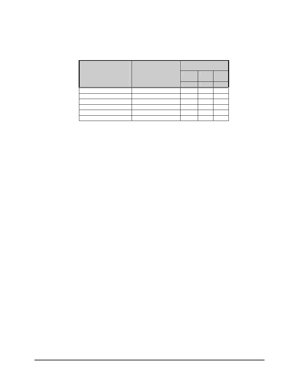
Table 3-3. Equalizer Control
Distance to DSX (Ft)
(See Note 1)
SW1
(See Note 2)
(applies only to
22–GA. PIC
Maximum Cable
Loss
4
3
2
[ABAM] Cable)
(dB at 772 kHz)
EC1
EC2
EC3
0 to 133
0.6
C
C
C
133 to 267
1.2
C
C
O
167 to 400
1.8
C
O
C
400 to 533
2.4
C
O
O
533 to 655
3.0
O
C
C
Test Clear
---
O
C
O
Notes:
1. Other bit combinations represent test modes and are not used for normal
operation.
2. Use maximum loss figures for other cable types.
Three fault outputs are provided on dry contact FORM C relays:
• Common
Equipment
• Modulator
• Demodulator
The faults are available on the fault connector on the modem rear panel. Generation of
these fault conditions is described in Chapter 4.
Fault indicators are also provided on TTL open collector drivers on the DS-1 connector.
• The TTL MOD fault indicates a Modulator fault or Common Equipment fault.
• The TTL DEMOD fault indicates a Demodulator or Common Equipment fault.
In order to facilitate testing of the modem when a DS-1 signal is not available, the output
of the clock recovery circuitry is replaced by a 1.544 MHz clock whenever loss of the SD
signal is detected. This allows the modem to generate its test signals at the proper data
rate.
A TXC-LOSS fault will occur in the Common Equipment fault menu whenever the
incoming data is missing.