5 mounting locations for external equipment, 6 installing the robot solenoid kit – Adept s600 Cobra User Manual
Page 79
Chapter 6: Optional Equipment Installation
1. Double-click the robot in the structure pane.
This will open up the object editor for the robot.
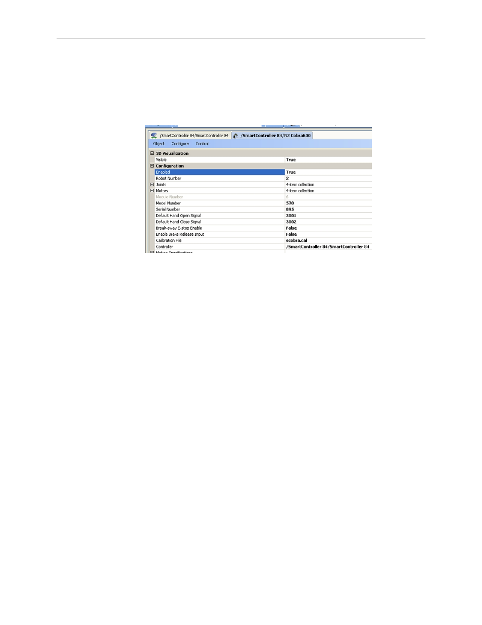
2. Select Break-away E-Stop Enable.
3. Change the value of this field to True.
Figure 6-8. Screen Shot with Break-away E-Stop Parameter Field
NOTE: When the Break-away E-Stop function has been enabled, you must connect
a normally-closed circuit to pins 1 and 2 of the ESTOP connector, as described
above. If this is not done, the system will be in an E-Stop condition and you will
not be able to enable power.
6.5 Mounting Locations for External Equipment
Three locations are provided for mounting user’s external equipment on the robot arm. The
first location is on the J1 Harness Support (top side of the inner link), a second is on the top
side of the outer link, and a third is on the bottom side of the outer link. Each location has a
set of four tapped holes. See Figure 7-5 and Figure 7-6 for the dimensions.
NOTE: The cover on the outer link must be removed for maintenance (lubrication),
so keep this in mind when mounting any external equipment to the outer link
cover.
For information on mounting cameras on the robot, see Installing the Camera Bracket Kit on
page 85.
6.6 Installing the Robot Solenoid Kit
This procedure describes how to mount the 24 V Robot Solenoid option on Adept Cobra s600
and s800 robots. The kit is available as Adept P/N 02853-000.
The robot has been pre-wired to accommodate a bank of two 24 VDC solenoid valves. Power
for the internal mounting is accessible via a connector mounted inside the outer link cover (see
Adept Cobra s600/s800 Robot, User’s Guide, Rev L1
Page 79 of 128