User electrical lines, 4 internal user connectors – Adept s600 Cobra User Manual
Page 73
Chapter 6: Optional Equipment Installation
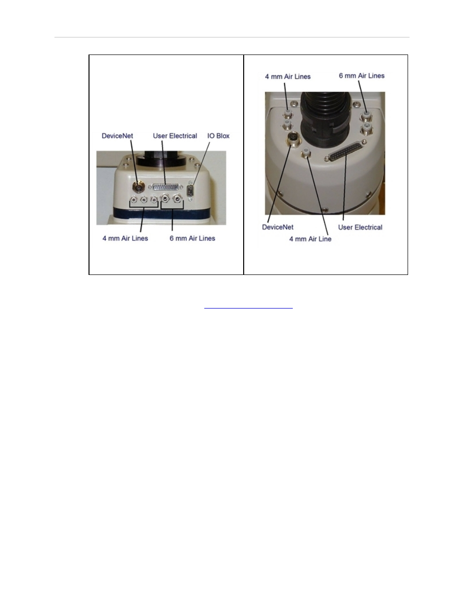
Figure 6-2. User Connectors on Joint 1
Figure 6-3. User Connectors on Joint 2
For information on the IO Blox connector, see Connecting Digital I/O to the System
on page 41. Also, refer to the
Adept IO Blox User’s Guide
for details.
User Electrical Lines
There is a 25-pin male connector (24 conductor) on the robot user panel on the back of Joint 1
for user electrical lines, see Figure 6-2. This connector is wired directly to a 25-pin female
connector on the top of the outer link, see Figure 6-3. These connectors can be used to run user
electrical signals from the user panel, through the robot, and up to the outer link.
Wire Specifications: Wire size: 0.1 mm
2
, Pin Numbers 1-24, 12 pairs, twisted in pairs as 1&2,
3&4, 5&6, . . . 23&24. Maximum current per line: 1 Amp.
6.4 Internal User Connectors
The internal user connectors, OP3/4, EOAPWR, and ESTOP, can be accessed with the Outer
Link cover removed—see Figure 6-4. The SOLND connector is located on the opposite of the
bulkhead area—see Figure 6-5.
Adept Cobra s600/s800 Robot, User’s Guide, Rev L1
Page 73 of 128