Parameters, Parameters –11 – Altera Serial Digital Interface (SDI) MegaCore Function User Manual
Page 99
Chapter 4: SDI Audio IP Cores
4–11
SDI Audio Extract MegaCore Function
February 2013
Altera Corporation
Serial Digital Interface (SDI) MegaCore Function
User Guide
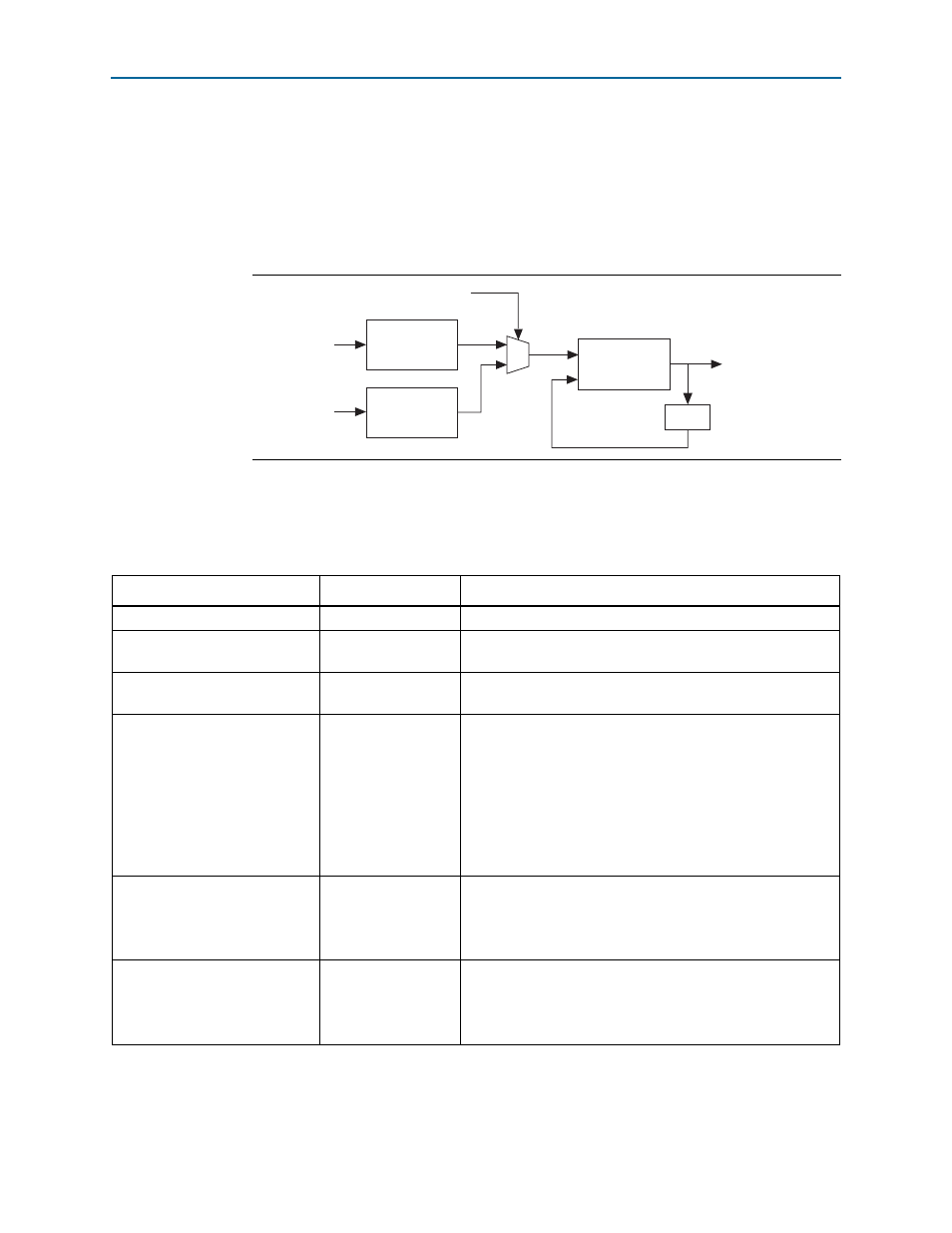
A digital PLL synchronizes this created clock to a 24-kHz reference source. For the
HD-SDI embedded audio, the 24-kHz reference source is the embedded clock phase
information. For the SD-SDI embedded audio, where the embedded clock phase data
is not present, you can create the 24-kHz reference signal directly from the video
clock.
shows the clock recovery block diagram.
Parameters
lists the parameters for the SDI Audio Extract MegaCore function.
Figure 4–3. Clock Recovery Block Diagram
Programmable
Divide
Digital
PLL
Clock Phase
Recovery
vid_clk
Video standard
3.072 MHz Output
24 KHz
Extracted
audio data
/128
SD
HD
Table 4–10. SDI Audio Extract MegaCore Function Parameters
Parameter
Value
Description
Channel status RAM
On or off
Turn on to store the received channel status data.
Include error checking
On or off
Turn on to enable extra error-checking logic to use the error
status register.
Include status register
On or off
Turn on to enable extra logic to report the audio FIFO status on
the fifo_status port or register.
Include clock
On or off
Turn on to enable the logic to recover both a sample rate clock
and a 64 × sample rate clock.
With HD-SDI inputs, the core generates the output by using the
embedded clock phase information.
With SD-SDI inputs, the core generates this output by using the
counters running on the 27MHz video clock. This generation
limits the SD-SDI embedded audio to being synchronous to the
video.
Include Avalon-ST interface
On or off
Turn on to include the SDI Clocked Audio Input MegaCore.
When you turn on this parameter, the Avalon-ST interface
signals in
appear at the top level. Otherwise, the
audio input signals in
appear at the top level.
Include Avalon-MM control
interface
On or off
Turn on to include the Avalon-MM control interface.
When you turn on this parameter, the register interface signals
in
appear at the top level. Otherwise, the direct
control interface signals in
appear at the top level.