Altera Serial Digital Interface (SDI) MegaCore Function User Manual
Page 119
Chapter 4: SDI Audio IP Cores
4–31
Design Example
February 2013
Altera Corporation
Serial Digital Interface (SDI) MegaCore Function
User Guide
3. The external waveform monitor (WFM700) displays the following observation:
a. Colorbar video pattern
b. Video format detect is 625i 50.00
c. Embedded audio standard detected is SMPTE272M
d. Audio channel pairs (1,2) and (3,4) are present
Transmit HD-SDI with Embedding of Audio Group 1 and 2
To transmit the HD-SDI video standard, follow these steps:
1. Set DIP switch[2:1] = 01
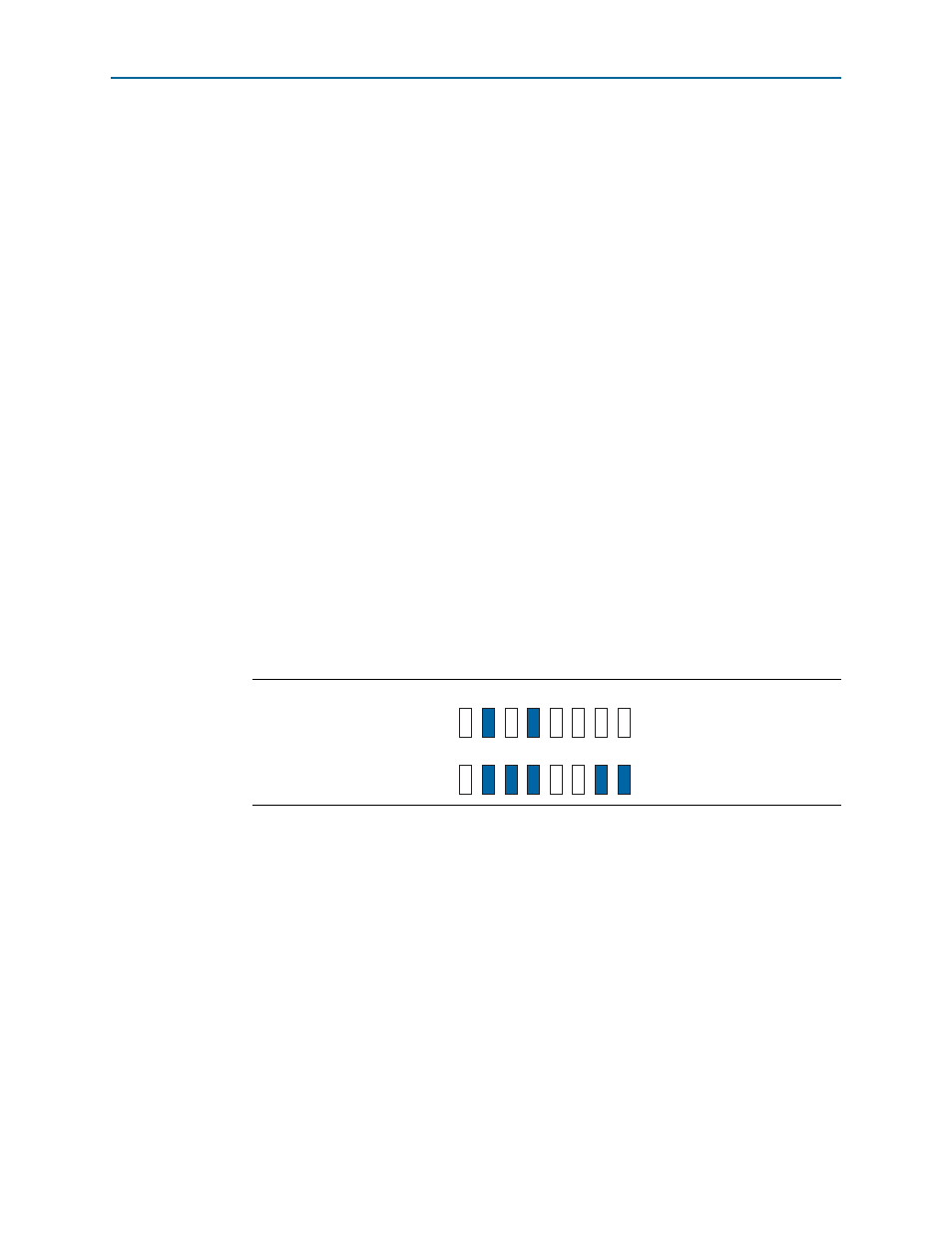
2. The demonstration runs and the LEDs indicate the following conditions:
a. LED D6 and D7 indicate the internal video pattern generator signal standard.
b. LED D8 and D9 indicate the receive video standard.
c. LED D16 blinks indicating the heartbeat of the receiver's recovered clock. The
frequency is blinking is slower than the previous demonstration.
d. LED D17 illuminates when the receiver is frame locked.
e. LED D18 illuminates when the receiver is TRS locked.
f. LED D19 illuminates when the receiver is alignment locked.
g. LED D23 and D22 illuminate when the data packet of audio groups 1 and 2 are
detected in the incoming SDI stream.
shows the condition of the LEDs.
3. The external waveform monitor (WFM700) displays the following observation:
a. Colorbar video pattern
b. Video format detect is 1080i 60.00
c. Embedded audio standard detected is SMPTE299M
d. Audio channel pairs (1,2), (3,4), (5,6) and (7,8) are present
Figure 4–12. Condition of LEDs for Transmitting HDI-SDI Video Standard
D6
D7
D8
D9
D10 D11 D12 D13
D16 D17 D18 D19 D20 D21 D22 D23