Altera Serial Digital Interface (SDI) MegaCore Function User Manual
Page 117
Chapter 4: SDI Audio IP Cores
4–29
Design Example
February 2013
Altera Corporation
Serial Digital Interface (SDI) MegaCore Function
User Guide
lists the function of each user-defined dual in-line package (DIP) switch
settings.
D18
Indicates that the receiver of the SDI duplex MegaCore function is TRS
locked.
D17
Indicates that the receiver of the SDI duplex MegaCore function is frame
locked.
D16
Indicates the recovered clock heartbeat of the receiver.
D13
Indicates the ancillary checksum failure.
D12
Indicates the ancillary parity failure.
D11
Indicates the channel status CRC failure.
D10
Indicates the audio packet failure.
D9-D8
Indicate the SDI receive video standards.
00 = SD-SDI, 01 = HD-SDI, 11 = 3G-SDI Level A, 10 = 3G-SDI Level B
D7-D6
Indicate the SDI transmit video standards.
00 = SD-SDI, 01 = HD-SDI, 11 = 3G-SDI Level A, 10 = 3G-SDI Level B
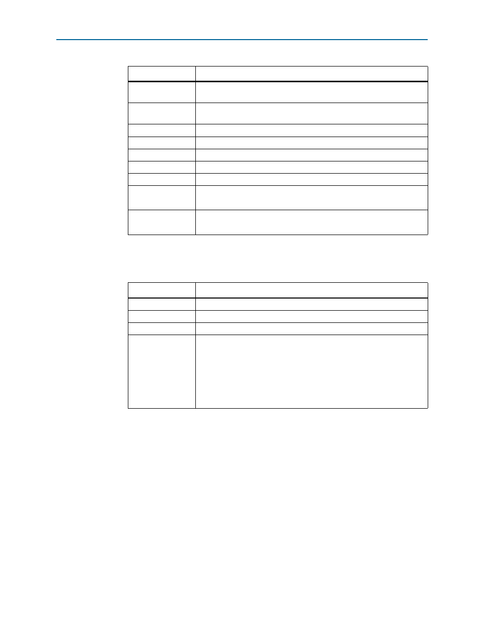
Table 4–31. Function of Each DIP Switch
DIP Switch
Description
8
Resets the system.
7
Resets the Audio Extract MegaCore function status registers.
6-3
Unused.
2-1
Configure the internally-generated video standards for both SDI transmitters.
00 = SD-SDI, 01 = HD-SDI, 11 = 3G-SDI Level A, 10 = 3G-SDI Level B
When 00, enables the embedding of audio group 1,
When 01, enables the embedding of audio group 1 and 2,
When 11, enables the embedding of audio group 1, 2, and 3,
When 10, enables the embedding of audio group 1, 2, 3, and 4
Table 4–30. Function of Each LED on the Stratix IV GX FPGA Development Board
LED
Description