Register maps, Register maps –18, Als in – Altera Serial Digital Interface (SDI) MegaCore Function User Manual
Page 106: Table 4–21, Appe
4–18
Chapter 4: SDI Audio IP Cores
Clocked Audio Input MegaCore Function
Serial Digital Interface (SDI) MegaCore Function
February 2013
Altera Corporation
User Guide
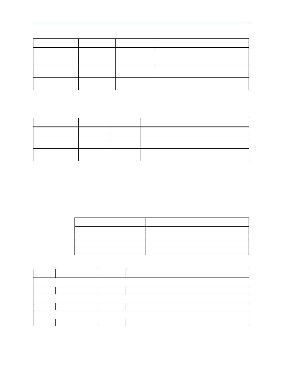
lists the direct control interface signals. The direct control interface is
internal to the audio extract component.
For register interface signals, refer to
. All SDI audio cores use the same
register interface signals.
Register Maps
list the register maps for the SDI Clocked Audio Input
MegaCore function.
aud_sop
[0:0]
Output
Avalon-ST start of packet signal. The MegaCore
function asserts this signal when it is starting a new
frame.
aud_eop
[0:0]
Output
Avalon-ST end of packet signal. The MegaCore
function asserts this signal when it is ending a frame.
aud_data
[23:0]
Output
Avalon-ST data bus. The MegaCore function asserts
this signal to transfer data.
Table 4–20. Avalon-ST Audio Signals (Part 2 of 2)
Signal
Width
Direction
Description
Table 4–21. Direct Control Interface Signals
Signal
Width
Direction
Description
channel0
[7:0]
Input
Indicates the channel number of audio channel 1.
channel1
[7:0]
Input
Indicates the channel number of audio channel 2.
fifo_reset
[7:0]
Input
Drive bit 7 high to reset the clocked audio input FIFO buffer.
fifo_status
[0:0]
Output
Assert this signal when the clocked audio input FIFO buffer
overflows.
Table 4–22. SDI Clocked Audio Input MegaCore Function Register Map
Bytes Offset
Name
00h
Channel 0 Register
01h
Channel 1 Register
02h
FIFO Status Register
03h
FIFO Reset Register
Table 4–23. SDI Clocked Audio Input MegaCore Function Register Map (Part 1 of 2)
Bit
Name
Access
Description
Channel 0 Register
7:0
Channel 0
RW
The user-defined channel number of audio channel 0.
Channel 1 Register
7:0
Channel 1
RW
The user-defined channel number of audio channel 1.
FIFO Status Register
7:0
FIFO status
RO
This sticky bit reports the overflow of the clocked audio input FIFO.