Signals, Signals –12 – Altera Serial Digital Interface (SDI) MegaCore Function User Manual
Page 100
4–12
Chapter 4: SDI Audio IP Cores
SDI Audio Extract MegaCore Function
Serial Digital Interface (SDI) MegaCore Function
February 2013
Altera Corporation
User Guide
Signals
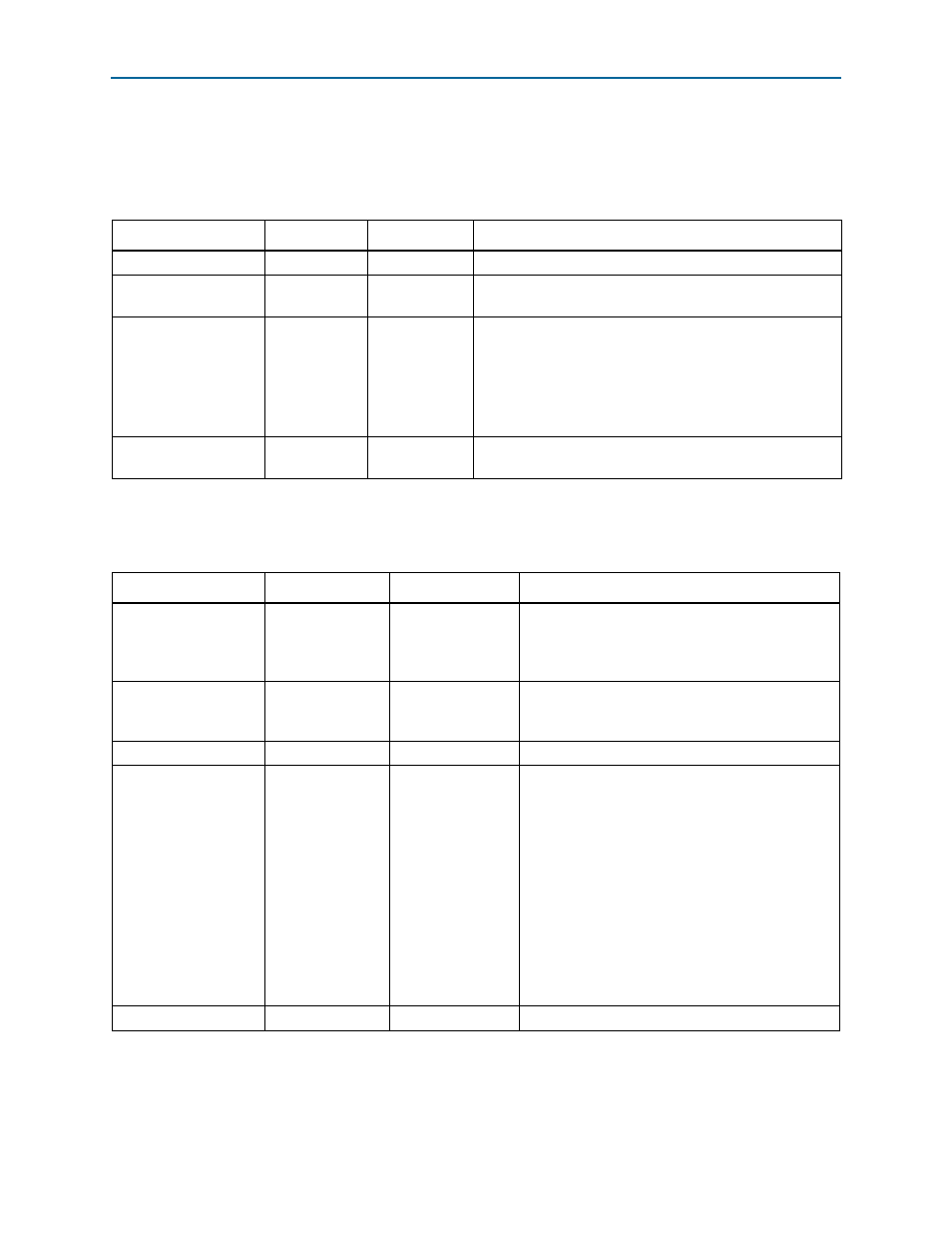
lists the clock recovery input and output signals for the SDI Audio Extract
MegaCore function.
shows the video input signals for the SDI Audio Extract MegaCore
function.
Table 4–11. Clock Recovery Input and Output Signals
Signal
Width
Direction
Description
reset
[0:0]
Input
This signal resets the system.
fix_clk
[0:0]
Input
Assert this 200 MHz reference clock when you turn on the
Include Clock parameter.
aud_clk_out
[0:0]
Output
The core asserts this 64 × sample rate clock (3.072 MHz
audio clock) when you turn on the Include Clock parameter.
You use this clock to clock the audio interface in synchronous
mode.
As the core creates this clock digitally, it is prone to higher
levels of jitter.
aud_clk48_out
[0:0]
Output
The core asserts this sample rate clock when you turn on the
Include Clock parameter.
Table 4–12. Video Input Signals
Signal
Width
Direction
Description
vid_clk
[0:0]
Input
The video clock that is typically 27 MHz for SD-SDI,
74.25 MHz or 74.17 MHz for HD-SDI, or 148.5 MHz
or 148.35 MHz for 3G-SDI standards. You can use
higher clock rates with the vid_datavalid signal.
vid_std
[1:0]
Input
Set this signal to 00b to indicate 10-bit SD-SDI
formats, 01b for 20-bit HD-SDI formats, 11b for 3G
Level A formats, and 10b for 3G-SDI Level B formats.
vid_datavalid
[0:0]
Input
Assert this signal when the video data is valid.
vid_data
[19:0]
Input
This signal carries luma and chroma information.
SD-SDI:
■
[19:10] Unused
■
[9:0] Cb,Y, Cr, Y multiplex
HD-SDI and 3G-SDI Level A:
■
[19:10] Y
■
[9:0] C
3G-SDI Level B:
■
[19:10] Cb,Y, Cr, Y multiplex (link A)
■
[9:0] Cb,Y, Cr, Y multiplex (link B)
vid_locked
[0:0]
Input
Assert this signal when the video is locked.