Cub Cadet I-Beam Style User Manual
Page 80
3-61
3
7.Remove the acorn lock nut and flat washer
securing the side belt cover to the tiller casing
using a 7/16” socket.
8.Remove the hex screw securing the belt cover
to the engine mounting bracket using a 3/8”
socket.
9.Remove the belt cover from the tiller.
10.Remove the hairpin and wave washer securing
the idler pulley rod to the idler bracket using a
pair of needle-nose pliers. See Figure 3-169.
11.Move the idler pulley rod to the lower hole in
the idler bracket.
12.Secure the idler pulley rod to the idler bracket
with the wave washer and hairpin removed
earlier.
13.Shift the gear selector to all the forward
modes.
14.Assemble the tiller in the reverse order above.
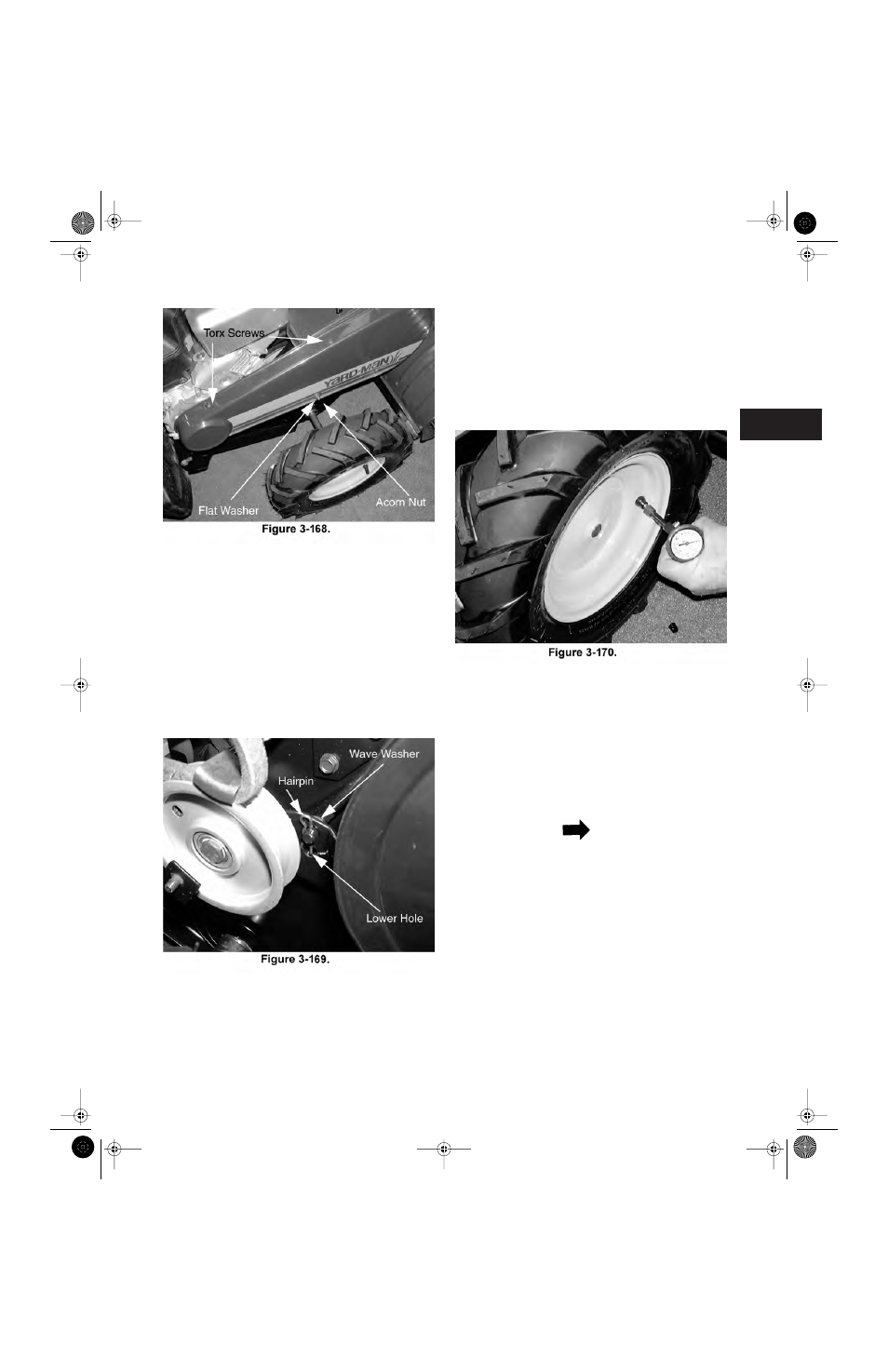
Tire Pressure
1.Remove the valve stem cap.
See Figure 3-
170.
2.Place a tire gauge over the end of the valve
stem and push down.
3.
Record the pressure (P.S.I.).
4.Examine the side walls of the tire and identify
the manufacturer’s recommended pressure.
5.Inflate or deflate the tires until the recom-
mended tire pressure has been achieved.
NOTE
Recommended tire pressure for this tiller is 20
P.S.I.
Gear Selector Positions
The shift selector handle is mounted left of
center on the upper handle bar.
a. By applying pressure to the shift selector han-
dle, the shift rod rotates the indicator bracket,
thus selecting a geared position in the trans-
mission. See Figure 3-171.
Tillers.fm Page 61 Tuesday, February 19, 2002 1:28 PM