Cub Cadet I-Beam Style User Manual
Page 249
6-50
21. Shut the log splitter off.
22. Make certain the face and back side of the
beam assembly are well lubricate where the
wedge assembly travels. See Figure 6-52.
Right Side—Correcting the
Adjustable Gib Shims
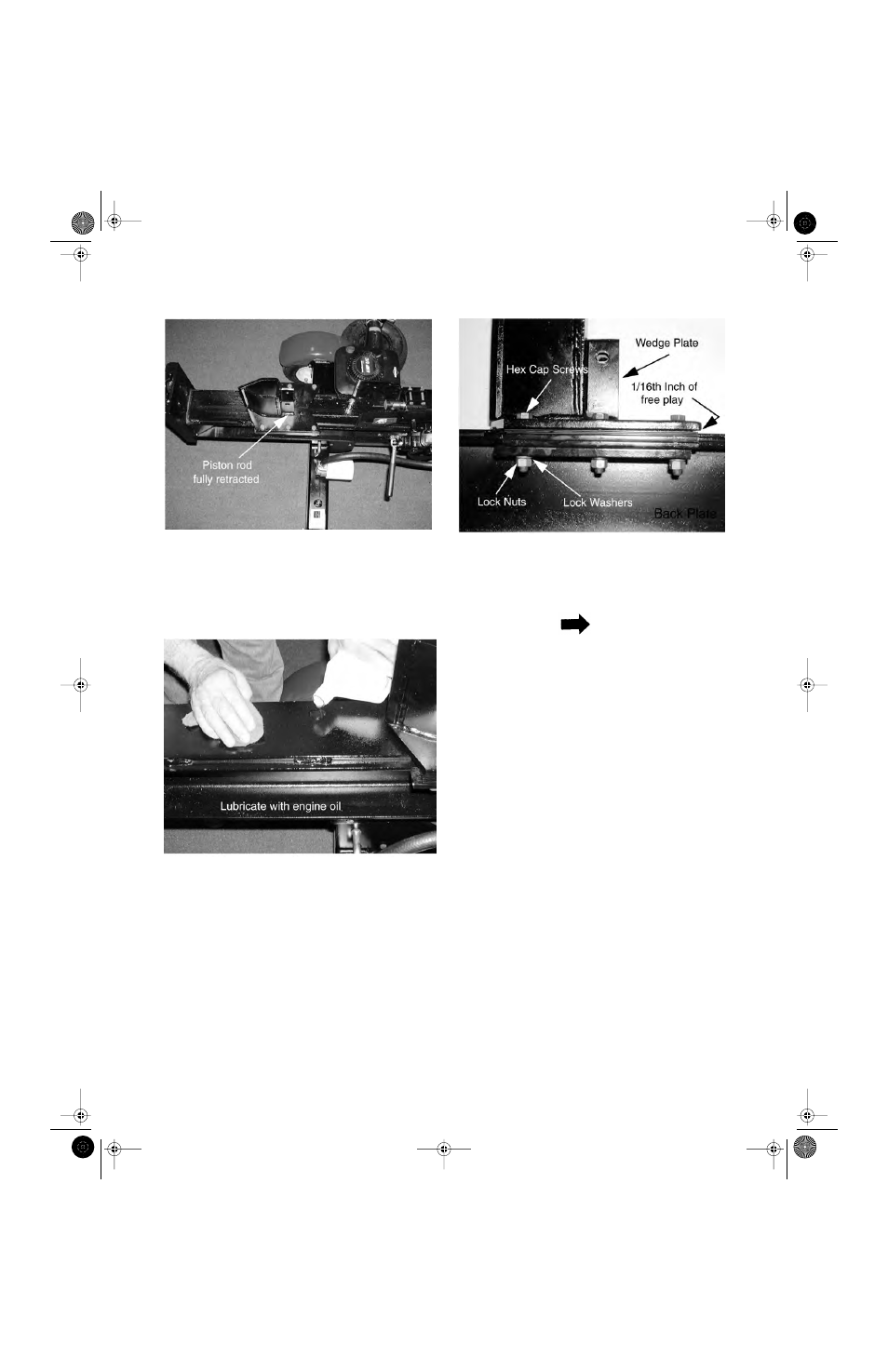
1. Make certain all three hex cap screws, lock
washers and lock nuts securing the wedge
plate, adjustable gib shims, fixed gib plates
and back plate are secure on the right side of
the wedge assembly using a 3/4" socket and a
3/4" wrench. See Figure 6-53.
2. Grasp the right side of the wedge assembly
from below the back plate and raise it up, mak-
ing certain there is not excessive tolerance.
NOTE
The wedge plate should not rise off the beam
face more than 1/16".
3. If the wedge plate does not rise more than
1/16" off the beam face proceed to the Correct-
ing the Gib Adjustments section.
4. If the wedge assembly rises off the beam more
than 1/16”, perform the following steps:
5. Remove all three hex cap screws, lock wash-
ers and lock nuts securing the wedge plate,
adjustable gib shims, fixed gib plates and back
plate using a 3/4" socket and a 3/4" wrench.
6. Remove the adjustable gib shim(s) required to
achieve the 1/16” tolerance.
7. Assemble the right side of the wedge assem-
bly in the reverse order above.
Left Side—Correcting the
Floating Gib Adjustments
IMPORTANT: Prior to performing this section,
make certain the beam face where the wedge
assembly travels is lubricated. See Figure 6-
54.
Figure 6-51.
Figure 6-52.
Figure 6-53.
Log Splitters 2.fm Page 50 Wednesday, February 20, 2002 1:35 PM