Cub Cadet I-Beam Style User Manual
Page 16
3-2
grease level. If the case is disassembled the
grease can be replaced. See Figure 3-1. For a
summary of specifications for Model 031, see
Table 3-1.
3-2.2 Clutch Adjustment.
Adjust clutch as follows:
WARNING
Disconnect spark plug wire from spark plug
and ground it against engine block (secure in V
slot) before making any adjustments or per-
forming maintenance.
NOTE
Do not overtighten control wire. Too much ten-
sion may cause it to break.
1.Hold the clutch grip so that the grip is down
against the handle. Adjust clutch control cable
so that the slack is taken out of the control
wire. Tighten two hex nuts at cable support
bracket. Control wire should now be straight.
2.With clutch grip released (neutral position), pull
starter cord several times. The tines should not
turn. If they do, adjust the hex nuts at the
clutch cable bracket. Check again for correct
adjustment.
3-2.3
Belt System.
Note the following:
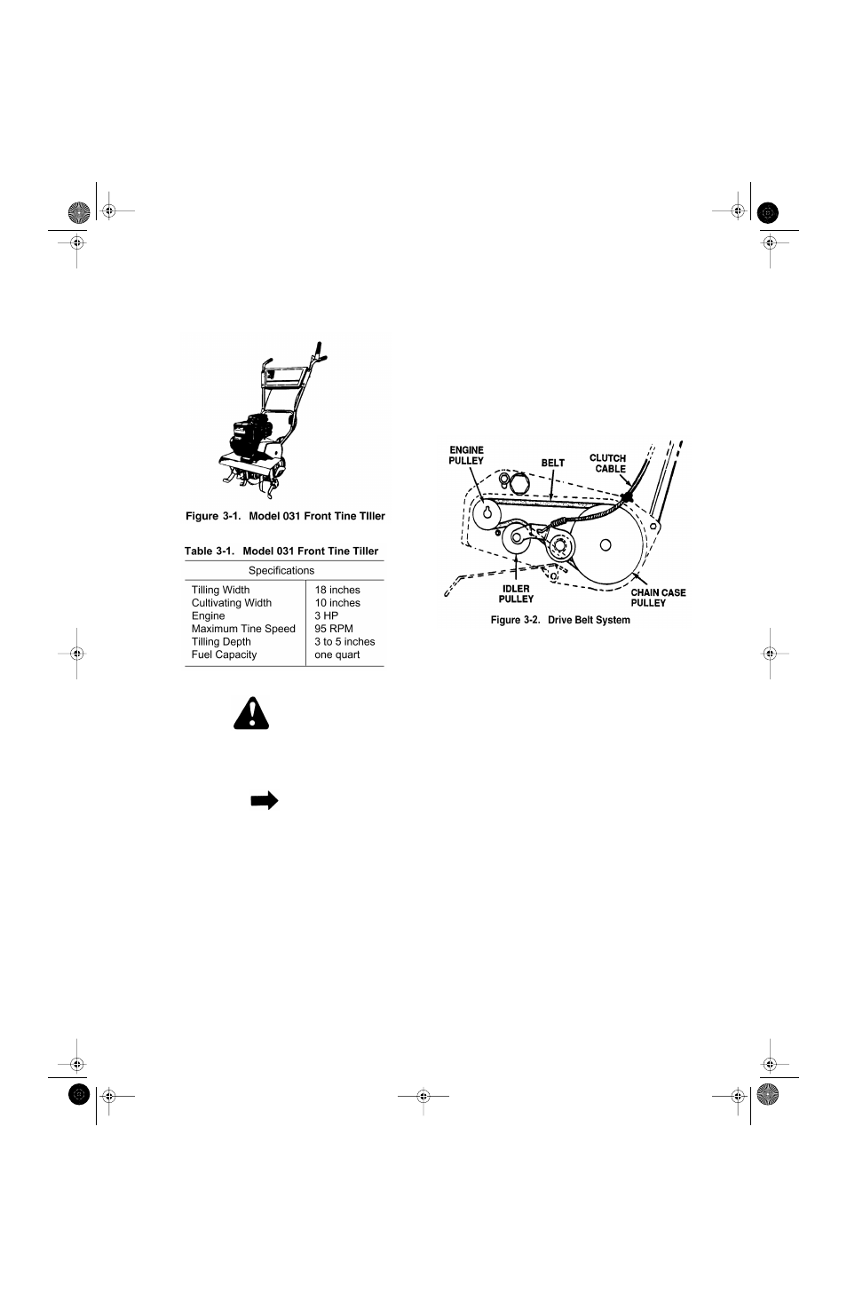
1.The clutch idler disengages the belt when you
release the clutch control lever. This will disen-
gage the tines and allow the tiller to be in a
neutral position. See Figure 3-2.
2.If the engine pulley is removed note how it is
assembled. The hub is to the inside. Check the
V-belt alignment between the engine pulley
and chain case pulley.
3-2.4 Belt Removal and Replacement.
1.Remove belt cover assembly by removing one
hex nut and lock washer, one self-tapping
screw, one hex bolt, flat washer and hex nut
and one hex bolt and external lock washer.
2.Lift belt cover assembly off tiller.
Be careful not
to bend or kink clutch cable.
3.Remove belt and position new belt on engine
pulley and chain case pulley. See Figure 3-2.
4.Upon reassembly of belt cover, place belt over
top of idler pulley and between engine pulley
and weld pin on belt cover assembly.
5.Fasten belt cover assembly in position.
Secure
with the hardware removed in step 1.
Tillers.fm Page 2 Tuesday, February 19, 2002 1:28 PM