Cub Cadet I-Beam Style User Manual
Page 45
3-27
3
NOTE
Upon reassembly, refer to your owners guide
for correct assembly of wire belt guard for your
model tiller.
NOTE
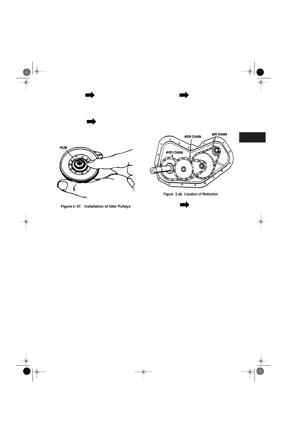
If the V-idler or flat idler pulleys are removed
for any reason, be sure to install with hub side
against idler bracket. See Figure 3-57.
3-6.4
Disassembly of Wheel Chain Case.
Disas-
semble as follows:
1.Remove chain case from tiller.
2.Remove self-tapping screws, two hex bolts,
lock washers and nuts from the outer edge of
the chain case.
3.Remove one hex bolt, lock washer and hex nut
from the center of chain case.
4.Remove remaining hex bolt, lock washer and
hex nut from the center of chain case.
5.Remove self-tapping screws from bearing
housing.
6.Slide bearing housing and bearing off input
shaft.
7.Separate halves of the chain case housing.
Be
careful not to damage chain case gasket.
Replace if necessary. See Figure 3-58.
NOTE
The drive system has three chain reduction
steps. Each step reduces the speed and
increases the torque or power down to the axle
shaft. The reduction is done with the use of a
#35 chain to a #420 chain and again to another
#420 chain.
NOTE
The chain case is lubricated with 10 ounces of
plastilube #0 grease to keep the bearings and
chains operating in a constant lubrication bath.
8.Push input shaft inward slightly.
Lift up on the
hub sprocket assembly and remove #35 chain
from sprocket. This will allow slack in the other
chains which can be removed by lifting off the
sprockets.
The hub sprocket assemblies can also be
removed from the housing during this proce-
dure. See Figure 3-59.
9.To disassemble hub sprocket assemblies slide
spacer out of bearing. On an arbor press
remove bearing by placing a spacer or similar
tool on the OD of bearing and press out. See
Figure 3-60.
Tillers.fm Page 27 Tuesday, February 19, 2002 1:28 PM