Log splitter wedge plate assembly adjustments – Cub Cadet I-Beam Style User Manual
Page 248
6-49
6
IMPORTANT: As normal wear occurs, the
wedge assembly must be adjusted to make
certain the tolerances are correct for smooth
operation. See Figure 6-48.
14. Place the beam assembly in the horizontal
position and lock it into place. See Figure 6-49.
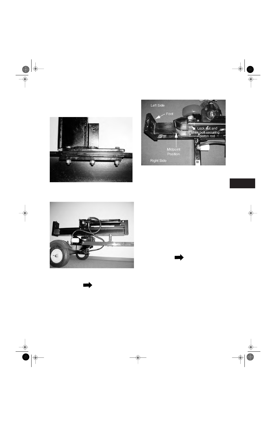
NOTE
The right and left sides of the log splitter are
determined standing behind the rectangular
foot of the log splitter, looking toward the hitch
coupler assembly. See Figure 6-50.
15. Start the log splitter and position the wedge
assembly at the midpoint between the rectan-
gular foot and the end of the hydraulic cylinder.
16. Shut the log splitter off.
17. Remove the hex lock nut from the hex bolt
securing the piston rod of the hydraulic cylin-
der to the wedge assembly using a 3/4" socket
and a 3/4" wrench.
18. Raise the piston rod enough to remove the hex
bolt securing the piston rod to the wedge
assembly.
19. Slowly lower the piston rod until the hydraulic
cylinder assembly rests on the face of the
beam assembly.
NOTE
The piston rod should not contact the face of
the beam.
20. Start the log splitter and retract the piston rod
fully. See Figure 6-51.
Figure 6-49.
Figure 6-50.
Figure 6-48.
Log Splitter Wedge Plate Assembly Adjustments
Log Splitters 2.fm Page 49 Wednesday, February 20, 2002 1:35 PM