2 fault exclusion, 2 protective (safety) stop, 1 protective (safety) stop requirements – Banner SC22-3E Safety Controller with Ethernet User Manual
Page 92: 2 protective (safety) stop hookup options
WARNING: . . . Input Devices with Solid State Outputs
The Safety Controller will not detect shorts between inputs or from an input to +24V, if the input signals on these
terminals are coming from input devices with Solid State Outputs.
It is the user’s responsibility to use a device that can detect these shorts (e.g., the Banner EZ-SCREEN® Light Screen
can detect a short between its two solid-state outputs or from each output to +24V).
WARNING: . . . Category 2 or 3 Input Shorts
Detection of a short between two input channels (contact inputs, but not complementary contacts), if they are supplied
through the same source (e.g., the same terminal from the Controller in a dual-channel, 3-terminal hookup, or from an exter-
nal 24V supply) is not possible, if the two contacts are closed.
Such a short can be detected only when both of the contacts are open and the short is present for at least 2 sec-
onds.
10.1.2 Fault Exclusion
An important concept within the category requirements of ISO 13849-1 is the “probability of the occurrence of the failure,” which can be
decreased using a technique termed “fault exclusion.” The rationale assumes that the possibility of certain well-defined failure(s) can be
reduced to a point where the resulting fault(s) can be, for the most part, disregarded—that is, “excluded.”
Fault exclusion is a tool a designer can use during the development of the safety-related part of the control system and the risk assess-
ment process. Fault exclusion allows the designer to design out the possibility of various failures and justify it through the risk assess-
ment process to meet the intent requirements of Category 2, 3 or 4. See ISO 13849-1/-2 for further information.
10.2 Protective (Safety) Stop
A Protective (Safety) Stop is designed for the connection of miscellaneous devices (not otherwise listed on the “Add Safety Device”
screen) that could include safeguarding (protective) devices and complementary equipment. This stop function is a type of interruption of
operation that allows an orderly cessation of motion for safeguarding purposes. The function can be either automatically or manually
activated and reset either manually or automatically.
10.2.1 Protective (Safety) Stop Requirements
The required safety circuit integrity level is determined by a risk assessment and will indicate the level of control performance that is
acceptable (e.g., Category 4, Control Reliability), see section
10.1 Safety Circuit Integrity and ISO 13849-1 (EN954-1) Safety Circuit Prin-
on page 90. The protective stop circuit must control the safeguarded hazard by causing a stop of the hazardous situation(s), and
removing power from the machine actuators. This is typically functional stop category 0 or 1 as described by ANSI NFPA 79 and
IEC60204-1.
10.2.2 Protective (Safety) Stop Hookup Options
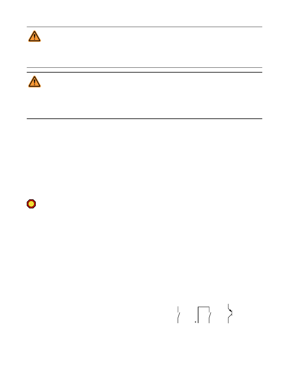
All figures show the input device in the OFF (Stop) state.
Single-Channel (1 terminal, 2 terminals or PNP device): These
circuits can typically meet ISO 13849-1 Category 2 requirements,
depending on the safety rating of the device(s). At a minimum, a
safety-rated device must be used to achieve a Category 2. The 1-
terminal and the PNP device circuits can not detect a short circuit
to another source of power. Two-terminal hookup uses pulse moni-
toring and can detect a short circuit to another source of power.
24V
OFF
SC22-3/-3E Safety Controller Instruction Manual
92
www.bannerengineering.com - tel: 763-544-3164
P/N 133487 rev. C