7 operating instructions, 1 monitoring controller operation, 3 display – Banner SC22-3E Safety Controller with Ethernet User Manual
Page 71: Controller information — onboard interface (obi), Run mode, Figure 47. run mode menu selections — obi
7 Operating Instructions
7.1 Monitoring Controller Operation
The Safety Controller can be operated using either the OBI or the PCI interfaces to monitor ongoing status.
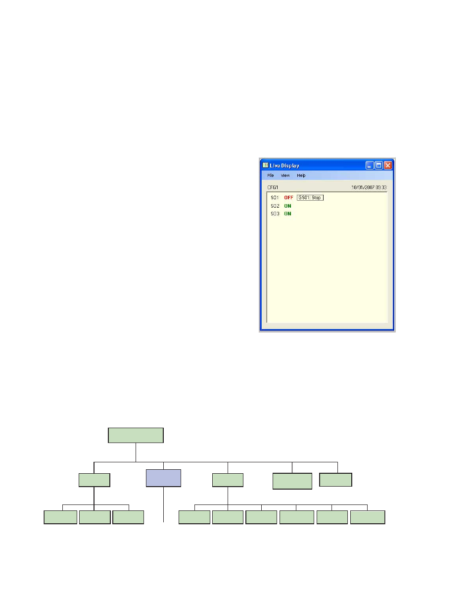
7.2 Display Controller Information — PC Interface (PCI)
To display real-time Run mode information on a PC, the computer
must be connected to the Controller, via a USB cable (see Section
1.3 for connection instructions). Open the Banner Safety Controller
program and click on the Live Display button in the PCI screen to
launch the Live Display screen. This feature continually updates Run
mode data and displays it in a pop-up screen.
The Live Display screen provides the same information that can be
viewed on the Controller’s LCD. It shows the status of each Safety
Output and reports on any input device or system event that can
cause a Safety Output to turn OFF.
Figure 46. Live Display screen — PCI
7.3 Display Controller Information — Onboard Interface (OBI)
To display current information on the Controller's Onboard Interface screen (OBI), use the Controller's arrow buttons to step through the
Run mode menu, as shown below.
System Menu
Run Mode
Model Number
software and
hardware versions
Configuration
Mode
(Section 5.3)
Configuration
Summary
Fault
Diagnostics
Clear
Fault Log
View
Fault Log
View Current
Faults
Status Output
Settings
Settings
Input/Output
Mapping
Terminal
Assignments
Set Display
Contrast
←
O
K
E
S
C
→
←
O
K
E
S
C
→
←
O
K
E
S
C
→
←
O
K
E
S
C
→
View Response
Times
View Network
Configuration
Checksum
Figure 47. Run mode menu selections — OBI
P/N 133487 rev. C
www.bannerengineering.com - tel: 763-544-3164
71