1 run mode screen—obi – Banner SC22-3E Safety Controller with Ethernet User Manual
Page 72
7.3.1 Run Mode Screen—OBI
The OBI Run mode screen displays current information about the Safety Controller, including:
• The configuration name
• Safety Output status
• Input status
• System status
• XM card status
Arrowhead designates
selected Safety Output
Configuration Name
Safety Output Status
Input Status Cause of
Output SO1 Status, or
Required Action
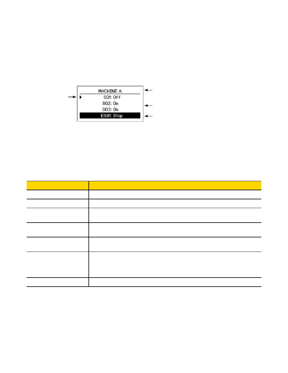
Figure 48. Run mode screen—OBI
Configuration Name: The top line of the display reads either the name of the configuration stored in the Safety Controller, if it has been
confirmed, or Configuration not confirmed, if it has not.
Safety Output Status: Lines 2, 3, and 4 of the screen display the status of the three Safety Outputs. The selected output will have a
small arrowhead to its left, on the screen. (The arrowhead scrolls through the Safety Outputs that are OFF, at 2-second intervals.) Line 5
of the display states the reason for the status of the selected Safety Output.
NOTE: Output faults are recoverable via a system reset (see section
7.5 System Resets and Lockout Conditions
on page 74).
Safety Output Status Message
Cause and/or Required Action
ON
The Safety Output is ON.
ON-Delay
The Safety Output will turn ON when the ON-delay time expires.
OFF
The Safety Output is OFF.
Line 5 of the display indicates the reason the Safety Output is OFF.
OFF-Delay
The Safety Output will turn OFF when the OFF-delay expires.
Line 5 of the display indicates the reason the Safety Output is in an OFF-delay.
Reset Needed
A manual reset operation needs to be performed.
Line 5 of the display indicates the name of the manual reset input to press.
Fault
A problem has been detected with the Safety Output. See section
9.3.1 Troubleshooting Fault Co-
on page 83 to find additional information regarding the fault.
If the fault is due to an external device monitor (EDM) fault, line 5 of the display indicates the name
of the EDM.
Enable Mode
Line 5 of the display indicates Enable Mode if a Safety Output is in Enable mode.
Input Status: If a Safety Output is OFF or turning OFF, line 5 of the display indicates information about the input that is keeping the
output OFF.
Line 5 also indicates when a manual reset operation needs to be performed.
NOTES:
• Line 5 changes to indicate each input when the status of more than one input must be displayed.
• Press the Up arrow button to pause the screen on the current input.
• Press the Down arrow button to change the last line to the next input. (Press the Down arrow button repeatedly to quickly cycle
through the inputs.)
SC22-3/-3E Safety Controller Instruction Manual
72
www.bannerengineering.com - tel: 763-544-3164
P/N 133487 rev. C