Banner SC22-3E Safety Controller with Ethernet User Manual
Page 13
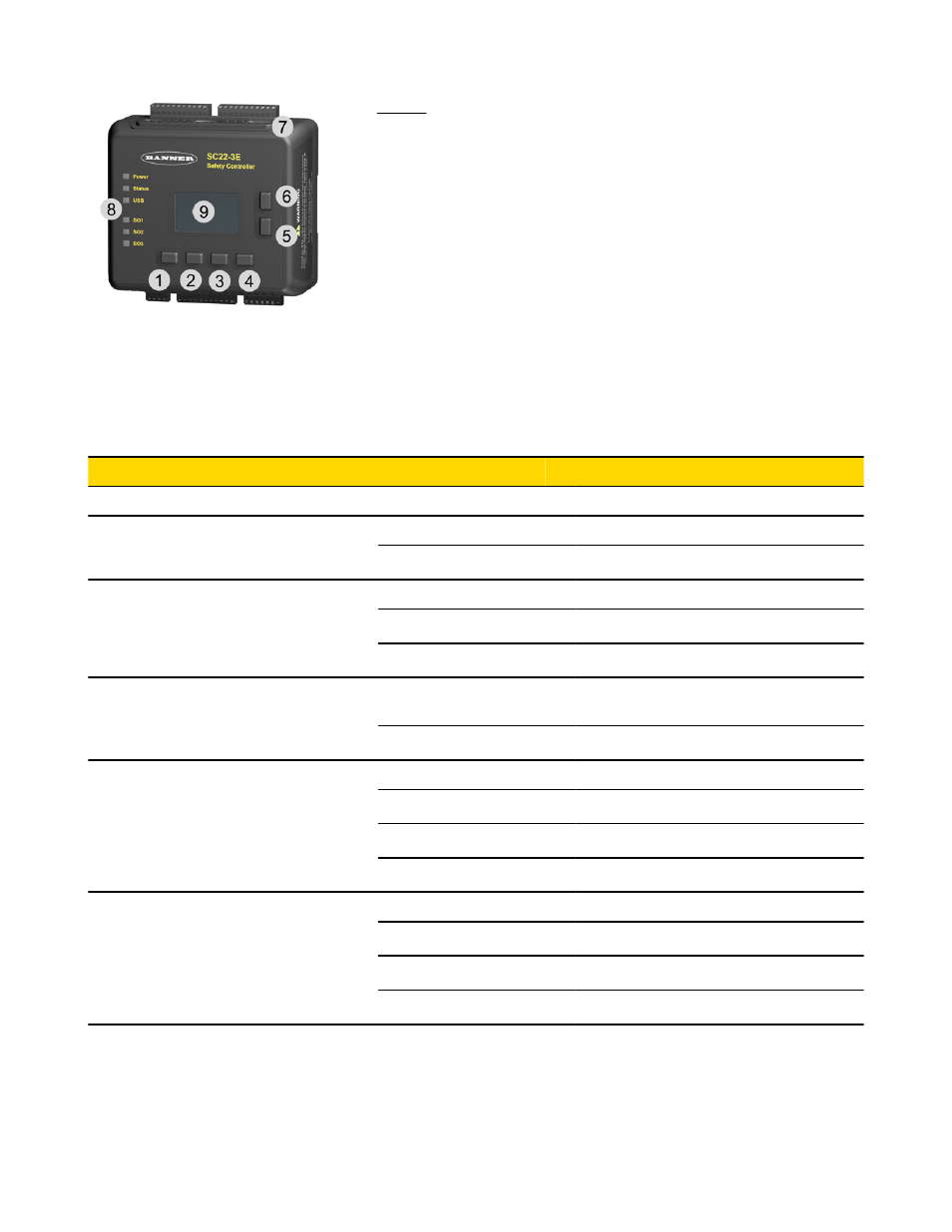
Legend:
1. Moves cursor to the left or selects settings.
2. Moves cursor to the pre-established point in the program to re-establish
a menu reference point.
3. Enters/stores the item highlighted in the display as the intended selection
or toggles a setting.
4. Moves cursor to the right or selects settings.
5. Moves cursor down or moves through a list to display individual list
items. Also used to select settings.
6. Moves cursor up or moves through a list to display individual list items.
Also used to select settings.
7. Ethernet connector indicators (Yellow and Green; Ethernet models only)
8. Status indicators
9. LCD display
Figure 5. Onboard Interface, including push buttons, LCD display and status indicators (model SC22-3E shown)
Status Indicator
Condition
Indicates Controller Status
All Indicators OFF
—
Initiation Mode
Power
ON Green
Power ON
OFF
Power OFF
Status (Controller Mode)
ON Red
Configuration mode
Flashing Red
Lockout mode
OFF
Run mode
USB or Tx/Rx (depending on model)
Flashing Green
Transmitting or receiving data (a link is establish-
ed with the PC)
OFF
Not transmitting or receiving data
Safety Output SO1, SO2, SO3
ON Green
Safety Output ON
ON Red
Safety Output OFF
Flashing Red
Safety Output fault detected
Flashing Green
Safety Output waiting for reset
Ethernet Connector (model SC22-3E
only)
Yellow OFF
No link
Yellow ON
Link OK
Green OFF
No activity
Green ON or flashing
Activity detected
SC22-3/-3E Safety Controller Instruction Manual
P/N 133487 rev. C
www.bannerengineering.com - tel: 763-544-3164
13