2 build a configuration – Banner SC22-3E Safety Controller with Ethernet User Manual
Page 54
5.1.2 Build a Configuration
To install the software on your computer, double-click on the Banner Safety Controller icon
. Read and understand the warning on
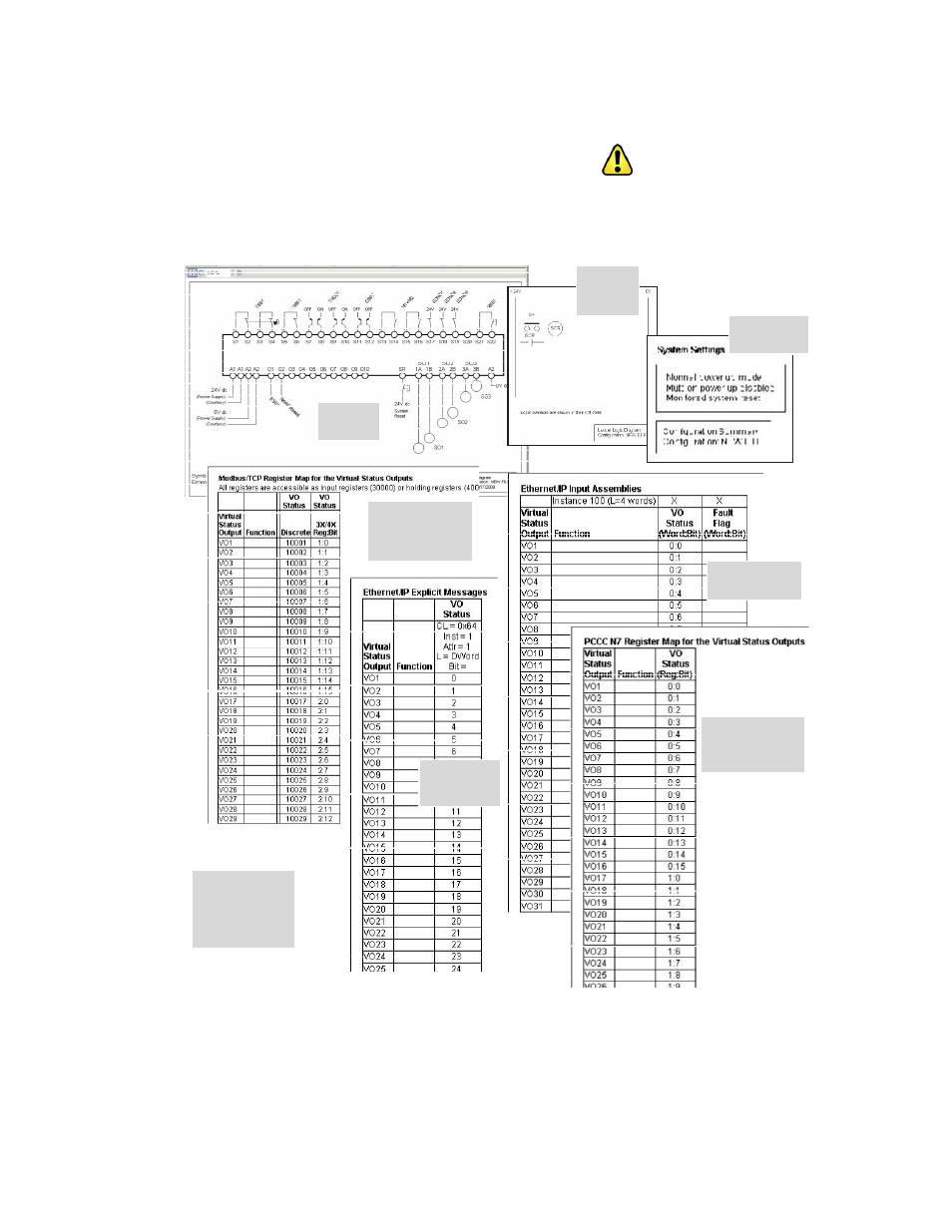
the Start-up page, and click OK. The main PCI screen should appear. The support documents, if opened at this point, show basic infor-
mation, and auto-populate as the configuration develops; see following figure. Not shown is the Notes document, which remains blank
until information is entered by the user, as desired.
Wiring
Diagram
Configuration
Summary
Ladder Logic
Diagram
Column and row
heading descriptions
for the Ethernet
forms are located in
Appendix D.
Modbus/TCP
Register Map for the
Virtual Status Outputs
EtherNet/IP Input
Assemblies
EtherNet/IP
Explicit Messages
PCCC N7
Register Map for the
Virtual Status Outputs
Figure 35. Configuration support documentation (notes not shown)
SC22-3/-3E Safety Controller Instruction Manual
54
www.bannerengineering.com - tel: 763-544-3164
P/N 133487 rev. C