Circuit types: contact and solid state circuits, Reset logic: manual or automatic reset, Terminal numbers: connecting the input devices – Banner SC22-3E Safety Controller with Ethernet User Manual
Page 29
Circuit Types: Contact and Solid State Circuits
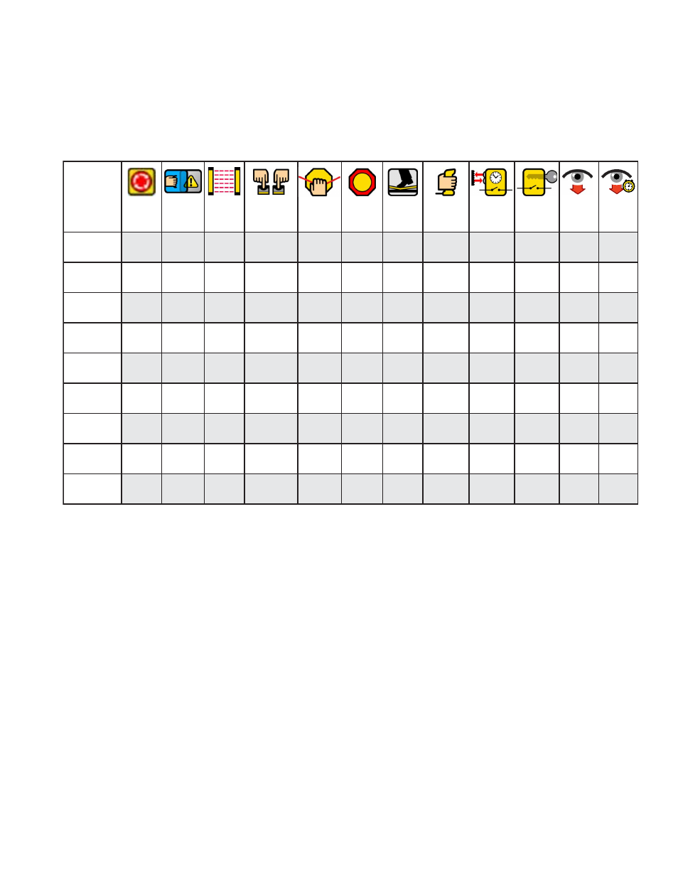
The table below depicts many of the input devices and circuit types the Controller can monitor. It highlights which of these properties can
be configured, and for which devices. More description of some of these topics is included in the following paragraphs.
Not all circuit types meet the Category 4 classification per ISO 13849-1; refer to section
10.1 Safety Circuit Integrity and ISO
13849-1 (EN954-1) Safety Circuit Principles
on page 90 for a discussion of safety circuit integrity levels.
E-Stop Safety
Gate
Optical
Sensor
Two-Hand
Control
Rope
Pull
Protect.
Stop
Safety
Mat
Enabling
Device
Mute
Sensors
Bypass
Switch
EDM
AVM
Circuit
Types
7
13
10
7
10
10
1
10
7
10
2
Reset
Logic
Auto/
Manual
Auto/
Manual
Auto/
Manual
Auto
Auto/
Manual
Auto/
Manual
Auto/
Manual
Auto
Auto
Auto
—
—
—
I/O
Mapping
I/O
I/O
I/O
I/O
I/O
I/O
I/O
I/O
I/I
I/I
I/O
2
I/O
Signal
COS*
S/C
S/C
S/C
S
S/C
S/C
—
S/C
S
S/C
S
Debounce
Times
Yes
Yes
Yes
Yes
Yes
Yes
Yes
Yes
Yes
Yes
No
No
Start Up
Test
—
Yes
Yes
—
—
—
—
—
—
—
—
Function
Time Limit
—
—
—
—
—
—
Yes
Yes
Yes
Yes
—
Muteable
—
Yes
Yes
Yes
—
Yes
Yes
—
—
—
—
Bypassable
—
Yes
Yes
Yes
—
Yes
Yes
—
—
—
—
—
—
—
* Refer to change-of-state table.
S = Simultaneous
C = Concurrent
Reset Logic: Manual or Automatic Reset
Safety input devices can be configured to require a manual reset before the Safety Output(s) they control are permitted to turn back ON.
This is sometimes referred to as “latch” mode because the Safety Output “latches” to the OFF state until a reset is performed. If a safety
input device is configured for automatic reset or “trip” mode, the Safety Output(s) it controls will turn back ON when the input device
changes to the Run state (provided that all other controlling inputs are also in the Run state).
Reset rules and types are discussed in section
on page 33.
Terminal Numbers: Connecting the Input Devices
The Controller needs to know what device signal lines are to be connected to which wiring terminals, so that it can apply the proper signal
monitoring methods, Run and Stop convention, timing rules, and fault rules. Although terminals are assigned automatically during the
configuration process, the terminal assignments can be changed manually, using either the Onboard Interface or the PC Interface.
SC22-3/-3E Safety Controller Instruction Manual
P/N 133487 rev. C
www.bannerengineering.com - tel: 763-544-3164
29