Finish the configuration – Banner SC22-3E Safety Controller with Ethernet User Manual
Page 57
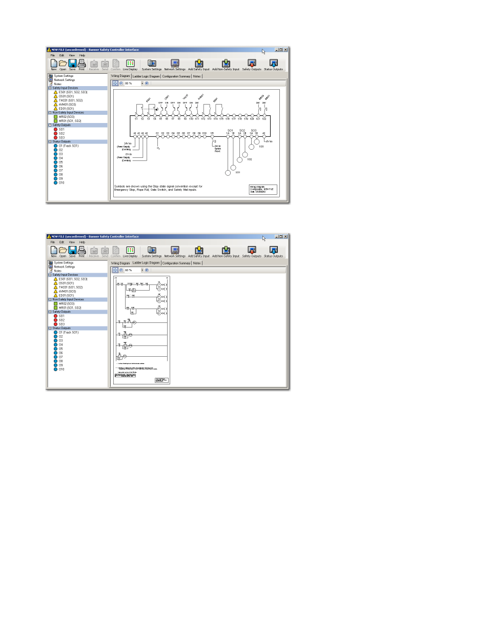
Figure 39. Wiring diagram populates with devices and output mapping
Figure 40. Ladder logic diagram develops along with wiring diagram
Finish the Configuration
Repeat the steps in the previous section to include additional safety or non-safety input devices.
Select Safety Outputs or Status Outputs from the tool bar to configure properties for these outputs, using the same menu-driven proc-
ess as that for the inputs.
Safety Output Properties — assigned individually for each Safety Output. Select the output to be configured from the drop-down menu
in the top field of the screen, and type in or select:
• Name
• Delay type and duration
Status Output Properties — assigned individually for each Status Output. Select the output to be configured from the drop-down menu
in the top field of the screen, and type in or select:
• Name
• Function
• Source (depending on function selected)
• Signal convention (depending on function selected)
SC22-3/-3E Safety Controller Instruction Manual
P/N 133487 rev. C
www.bannerengineering.com - tel: 763-544-3164
57