6 adjustable valve monitoring (avm) function – Banner SC22-3E Safety Controller with Ethernet User Manual
Page 39
Bypass Time Limit. A bypass function time limit can be established to limit how long the safety input device bypass is active. The time
limit can be adjusted from 1 second to 12 hours and cannot be disabled. Only one time limit can be set, and this limit will apply to all
safety devices that are bypassed. At the end of the time limit, Safety Output control authority is handed back to the bypassed safety input
devices.
Two-Hand Control Bypassing. If a Two-Hand Control input is actuated while the input is being bypassed, the Safety Controller will lock
out and issue a Stop signal. This ensures that the operator does not mistake that the Two-Hand Control is functional and is aware that
the bypassed Two-Hand Control is no longer providing the safeguarding function.
Mute-Dependent Override. When this option is enabled, and a mute sensor is mapped to the safety input device, and the safety input
device is in the STOP state, at least one of the Mute sensors must be in the Mute (Run) state in order to start a new bypass cycle. If the
conditions are right for bypass, the mute Status Output indicator (if configured) will start flashing at 1 Hz. If this option is disabled, the
Safety Input is not required to be in the Stop state and the mute sensors need not be blocked, in order to start a new bypass cycle.
Light
Screen
Mute
Sensor 1 (2)
Mute
Sensor 2 (1)
Bypass
Switch
Safety
Output
BypassTime
Expired
BypassTime
Expired
BypassTime
Expired
Don’t Care
Figure 20. Timing logic: Light screen with mute sensors and bypass switch
4.6.6 Adjustable Valve Monitoring (AVM) Function
Adjustable Valve (Device) Monitoring function is similar in function to One-Channel External Device Monitoring (1-channel EDM, see
section
4.7.1 External Device Monitoring (EDM)
on page 40). The function monitors the state of the device(s) that are controlled by the
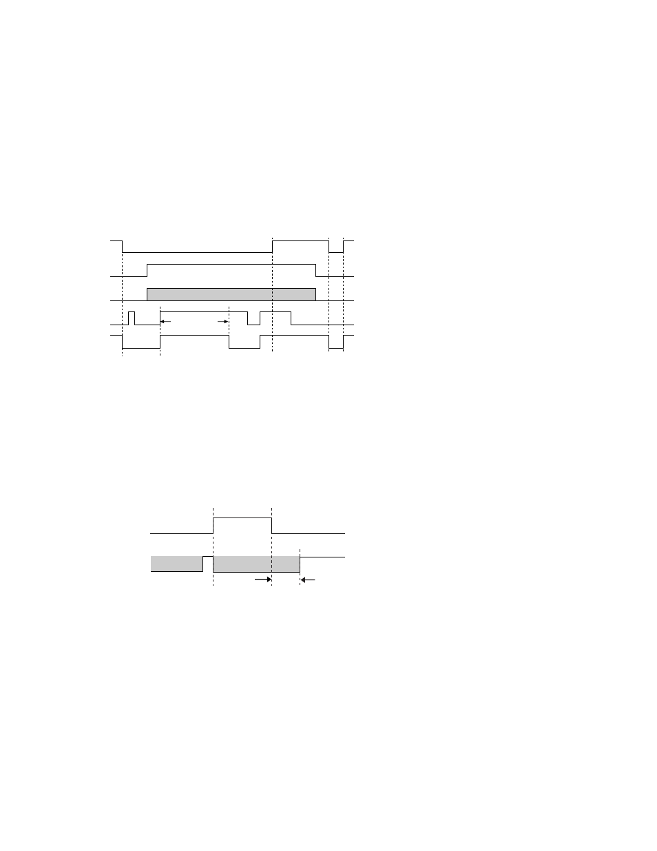
Safety Output to which the function is mapped. When the Safety Output turns OFF, the AVM input must be high/ON (+24V dc applied)
before the AVM timer expires or a lockout will occur. The AVM input must also be high/ON when the Safety Output attempts to turn ON or
a lockout will occur. See figure below; note that the 100 ms to 5 second time period is adjustable in 50 ms intervals (default is 100 ms).
Safety Output
100 ms
to
5 sec.
100 ms
to
5 sec.
100 ms
to
5 sec.
Don’t Care
Don’t Care
ON
OFF
Closed
Open
AVM
Figure 21. Timing logic: AVM function
The Adjustable Valve (Device) Monitoring function is useful for dynamically monitoring devices under control of the Safety Output that
may become slow, "sticky," or fail in an energized state or position and whose operation needs to be verified after a Stop signal occurs.
Example applications include single- or dual-solenoid valves controlling clutch/brake mechanisms, and position sensors that monitor the
home ("safe") position of a linear actuator.
Synchronization or checking a maximum differential timing between two or more devices (e.g., dual valves) can be achieved by mapping
multiple AVM functions to one Safety Output and configuring the AVM timer to the same values. Any number of AVM inputs can be
mapped to one Safety Output. An input signal can be generated by a hard/relay contact or a solid-state PNP output.
SC22-3/-3E Safety Controller Instruction Manual
P/N 133487 rev. C
www.bannerengineering.com - tel: 763-544-3164
39