3 perimeter guarding and pass-through hazards, Reducing or eliminating pass-through hazards, 6 safety input function – Banner SC22-3E Safety Controller with Ethernet User Manual
Page 35: 1 internal logic
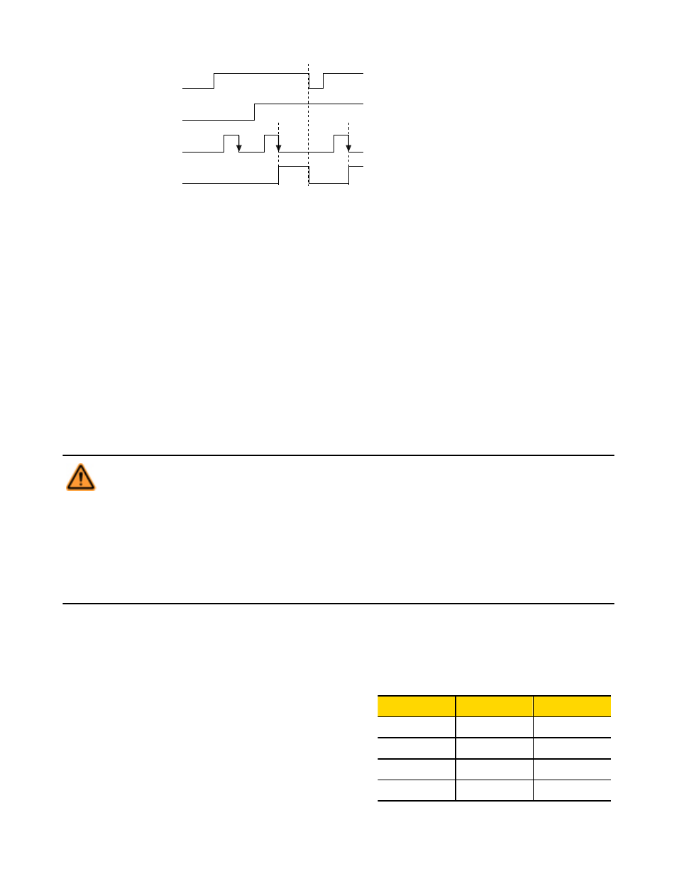
Safety Device 1
Manual Monitored Reset
Safety Device 2
Manual Monitored Reset
Manual Reset
Safety Output
Figure 16. Timing logic: Safety Outputs with a common reset, mapped to the same Safety Output
4.5.3 Perimeter Guarding and Pass-Through Hazards
A "pass-through hazard" is associated with applications, such as perimeter guarding, where personnel may pass through a safeguard
(which issues a stop command to remove the hazard), and then continue into the guarded area, where their presence is no longer detec-
ted. The related danger becomes the unexpected start or restart of the machine while personnel are within the guarded area.
Reducing or Eliminating Pass-Through Hazards
Eliminate or reduce pass-through hazards whenever possible. While it is recommended to eliminate the pass-through hazard altogether,
this may not be possible due to machine layout, machine capabilities, or other application considerations.
• One solution is to ensure that personnel are continually sensed while within the hazardous area. This can be accomplished by
using supplemental safeguarding, such as described by the ANSI B11 series of safety requirements or other appropriate standards.
• An alternate method is to ensure that when the safeguarding device is tripped, it will latch (manual reset), and will require a
deliberate manual action to reset. This method of safeguarding relies upon the location of the reset switch as well as safe work practi-
ces and procedures to prevent an unexpected start or restart of the guarded machine.
WARNING: . . . Perimeter Guarding Applications
If the application could result in a pass-through hazard (e.g., perimeter guarding), either the safeguarding device or
the guarded machine's MSCs/MPCEs must cause a Latched response following a Stop command (e.g., interruption
of the sensing field of a light curtain, or opening of an interlocked gate/guard). The reset of this Latched condition may
only be achieved by actuating a reset switch that is separate from the normal means of machine cycle initiation. The switch
must be positioned as described in this document.
Lockout/Tagout procedures per ANSI Z244.1 may be required, or additional safeguarding, as described by ANSI B11
safety requirements or other appropriate standards, must be used if a passthrough hazard can not be eliminated or reduced
to an acceptable level of risk. Failure to observe this warning could result in serious bodily injury or death.
4.6 Safety Input Function
4.6.1 Internal Logic
The Controller’s internal logic is designed so that a Safety Output can turn
ON only if all the controlling safety input device signals and the Controller’s
self-check signals are in the Run state and report that there is no fault con-
dition.
The table at right illustrates the logic for two safety input devices that are
mapped to control Safety Output 1. If either safety input device is in the
Stop state, the Safety Output will be OFF. When both safety inputs and the
Controller are in the Run state, Safety Output 1 will be ON.
Safety Input 1
Safety Input 2
Safety Output 1
Stop
Stop
OFF
Stop
Run
OFF
Run
Stop
OFF
Run
Run
ON
SC22-3/-3E Safety Controller Instruction Manual
P/N 133487 rev. C
www.bannerengineering.com - tel: 763-544-3164
35