5 i/o mapping: the i/o control relationship, 7 system settings – Banner SC22-3E Safety Controller with Ethernet User Manual
Page 18
WARNING: . . . Virtual Status Outputs
The Virtual Status Outputs are not Safety Outputs and can fail in either the ON or the OFF state. They must never be used
to control any safety-critical applications. If a Virtual Status Output is used to control a safety-critical application, a
failure to danger is possible and could lead to serious injury or death.
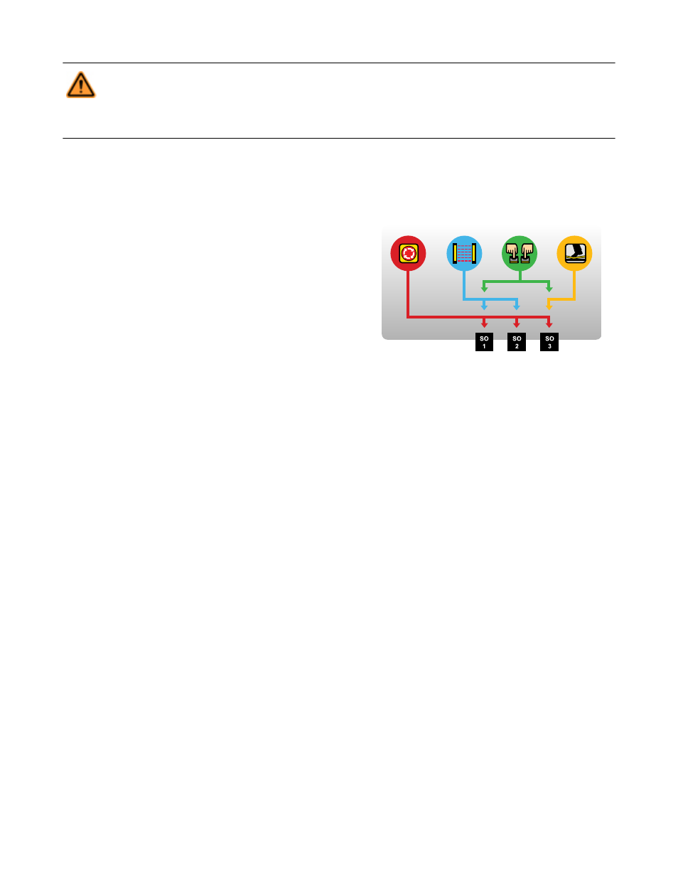
2.6.5 I/O Mapping: the I/O Control Relationship
The term “map” implies a control logic relationship between an input and an output or between an input and another input, where the
state of the first input determines the state of the output or of the second input.
Inputs Mapped to Outputs. The following devices can be mapped directly
to the Safety Outputs:
Figure 8. Input and Output mapping
• Emergency stop buttons
• Safety gate switches
• Optical sensors
• Two-hand control devices
• Safety mats
• Protective stop switches
• Rope pulls
• Enabling devices
• External device monitoring
• ON/OFF devices
• Manual reset devices
• Solenoid or press safety valves
• Cancel OFF-delay devices
Inputs Mapped to Inputs. Muting sensors and bypass switches work in conjunction with certain safety input devices to temporarily sus-
pend the Stop signal of a safety input device. These sensors and switches are mapped directly to the safety inputs; they are then indirect-
ly mapped to the Safety Output(s) that the muted safety inputs control (see section
2.7 System Settings
The Controller’s system settings define parameters for both the configuration file and the Controller. These settings include:
• Configuration name
• Author’s name
• Power-up mode
• Mute on power-up enable
• Monitored system reset
Configuration Name
The configuration name identifies the configuration that will be used in a Safety Controller application. The configuration name can be
displayed on the Controller and will be useful to be sure that the configuration in a Controller is the correct one.
Author’s Name
The author’s name may also be helpful when questions arise about configuration settings.
Power-Up Mode (Operational Characteristics When Power Is Applied)
The Controller provides three power-up mode types to choose from, to determine how the Controller will behave just after power is sup-
plied. These modes are: Normal, Automatic, and Manual.
• Normal Power-Up Mode (default). In normal power-up mode, after power is applied:
• Only those Safety Outputs that have automatic reset inputs will turn ON.
• Safety Outputs that have one or more manual reset inputs will turn ON only after a manual (latch) reset operation is performed.
• Exception: Two-hand control inputs, bypass inputs, and enabling device inputs must be seen to be in the Stop state at power-up,
regardless of the power-up mode selection. If these are seen to be in the Run state at power-up, the outputs will remain OFF.
• Automatic Power-Up Mode. In automatic power-up mode, after power is applied:
SC22-3/-3E Safety Controller Instruction Manual
18
www.bannerengineering.com - tel: 763-544-3164
P/N 133487 rev. C