1 verifying system operation – Banner SC22-3E Safety Controller with Ethernet User Manual
Page 76
8.2.1 Verifying System Operation
The commissioning checkout procedure must be performed by a Qualified Person, as defined in the glossary of this manual. It
must be performed only after configuring the Controller and after properly installing and configuring the safety systems and
safeguarding devices connected to its inputs (per section
10 Input Device and Safety Category Reference
on page 90 and the appropri-
ate standards).
The commissioning checkout procedure is performed on two occasions:
1. When the Controller is first installed, to ensure proper installation, and
2. Whenever any maintenance or modification is performed on the System or on the machinery being guarded by the System, to
ensure continued proper Controller function. (See section
8.1 Schedule of Required Checkouts
For the initial part of the commissioning checkout, the Controller and associated safety systems must be checked
without pow-
er being available to the guarded machine. Final interface connections to the guarded machine cannot take place until these systems
have been checked out.
Verify that:
• The Safety Output leads are isolated — not shorted together, and not
shorted to power or ground;
• If used, external device monitoring (EDM) connections have been connec-
ted to +24V dc via the N.C. monitoring contacts of the device(s) connec-
ted to the Safety Outputs, as described in section
on page 40 and the wiring diagrams.
• The proper Controller configuration file for your application has been in-
stalled into the Safety Controller; and
• All connections have been made according to the appropriate sections
and comply with NEC and local wiring codes.
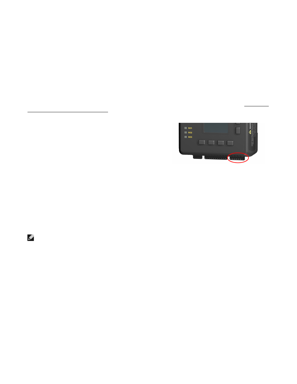
Figure 50. Safety Output terminal block
This procedure will allow the Controller and the associated safety systems to be checked out, by themselves, before permanent connec-
tions are made to the guarded machine.
8.3 Initial Setup, Commissioning and Periodic Checkout
NOTE: If any of the Status Outputs are mapped to functions within the configuration, monitor the function of each Status
Output as the associated operation is tested.
1. Configure the machine so that the indicators for the Safety Outputs (SO1, SO2, and SO3) of the Safety Controller and for the
associated output devices can be observed and verified to operate correctly and without risk of injury.
Do not apply power to the
Safety Controller or to the guarded machine now.
2. Safety System and Safeguarding Device Checkout
a. Verify that the guarded machine is of a type and design compatible with this safeguarding system, as described on page 1.
b. Verify the installation and perform the checkout procedures for the external safety/safeguarding systems and devices con-
nected to the Safety Controller inputs as described by the appropriate manuals. Do not proceed until all checkout procedures
are completed successfully and all problems have been corrected.
c. Verify that:
• Access to any dangerous parts of the guarded machine is not possible from any direction not protected by the safeguard-
ing system, hard guarding, or supplemental safeguarding, and that
• Supplemental safeguarding and hard guarding, as described by the appropriate safety standards, are in place and func-
tioning properly.
d. Verify that all Reset switches are mounted outside and in full view of the guarded area, out of reach of anyone inside the
guarded area, and that means of preventing inadvertent use is in place.
SC22-3/-3E Safety Controller Instruction Manual
76
www.bannerengineering.com - tel: 763-544-3164
P/N 133487 rev. C