4 common wire installation – Banner SC22-3E Safety Controller with Ethernet User Manual
Page 49
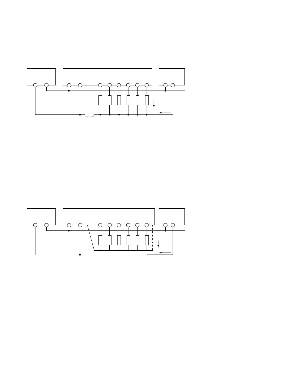
4.7.4 Common Wire Installation
To avoid nuisance lockout codes 1.1, 1.2, or 1.5, give thoughtful consideration to the leadwire resistance of the 0V common wire and to
the currents flowing in that wire. Notice the location of the block in the diagram below representing leadwire resistance (RL).
Power Supply
Other
Equipment
Safety Controller
0V
0V
SO1
SO2
SO3
24V dc
24V dc
Load
Current
6 Output Loads
RL
Other
Current
RL = Leadwire resistance
Vo = Voltage > 0.9V when a
safety output is off (or pulsing off)
may cause error codes 1.1, 1.2,
1.5
Figure 32. DC-common wire installation
When a safety output turns OFF, the voltage at the output terminal (VO ) must drop below 0.9V with respect to the 0V terminal of the
Safety Controller. If the voltage is higher than this, the Controller may think that the output is still on and lock out.
This residual voltage can occur in several ways:
• a large current flowing in a shared 0V conductor by other safety outputs that are still on,
• a common mode current flowing from other equipment, or
• either of these, along with a 0V wire that is too small, or too long.
The solution is to increase the wire gauge of the 0V common wire and/or consider using the courtesy 0V terminals on the Safety Control-
ler as shown in the following diagram. This eliminates the influence of common mode current from other equipment.
Power Supply
Other
Equipment
Safety Controller
0V
0V
SO1
SO2
SO3
24V dc
24V dc
Load
Current
6 Output Loads
Other
Current
Improved Wiring Scheme:
- Either dashed wire is OK
- Consider heavier wire
- Better: Use separate 0V return
for each pair of outputs (a+b)
when heavily loaded
1
a
1
b
2
a
2
b
3
a
3
b
Figure 33. DC-common wire installation: eliminating the influence of common mode current from other equipment
SC22-3/-3E Safety Controller Instruction Manual
P/N 133487 rev. C
www.bannerengineering.com - tel: 763-544-3164
49