8 rope/cable pull, 1 rope/cable pull installation guidelines – Banner SC22-3E Safety Controller with Ethernet User Manual
Page 109
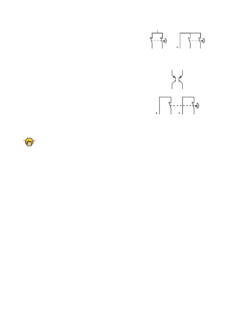
Dual-Channel (2 or 3 terminals): This circuit typically can meet
ISO 13849-1 Category 3 requirements, depending on the design
and installation of the switch. Dual-channel 3-terminal hookup uses
pulse monitoring and can detect a short circuit to another source of
power. Both 2- and 3-terminal hookup can detect a short between
channels when the contacts are open if the short is present longer
than 2 seconds.
24V
Dual-Channel (PNP device): This circuit can meet ISO 13849-1
Category 2, 3, or 4 requirements depending on the safety rating,
installation, and the fault detection (e.g., short circuit) capabilities
of the switch. The Safety Controller does not provide short circuit
detection in this configuration.
ON
ON
Dual-Channel (4 terminals): This circuit can meet ISO 13849-1
Category 4 requirements, depending on the safety rating and the
installation of the switch. This circuit can detect a short circuit be-
tween channels or to another source of power.
10.8 Rope/Cable Pull
Rope pull (cable pull) emergency stop switches use steel wire “rope”; they provide emergency stop actuation continuously over a
distance, such as along a conveyor.
Rope pull emergency stop switches have many of the same requirements as emergency stop push buttons, such as “positive opening”
(or direct-opening) operation, as described by IEC 60947-5-1. See section
10.7 Emergency Stop Push Buttons
tional applicable information.
It is recommended to use rope pull emergency stop switches that have the capability not only to react to a pull in any direction, but also to
slack or a break of the rope. Typically, this is accomplished by separate contacts within the switch. When the rope is properly tensioned,
both contacts of the switch are closed. When the rope is pulled, the positive-break contacts open. If the rope breaks or goes slack, the
second set of contacts opens; see section
10.8.2 Rope Pull Hookup Options
on page 111.
Some rope pull emergency stop switches provide a latching function that requires a manual reset after actuation. If using a switch that
does not provide a latching function after the rope is released, a separate latching circuit is required, which can be provided by the Safety
Controller.
10.8.1 Rope/Cable Pull Installation Guidelines
• The wire rope should be easily accessible and visible along its entire length. Markers or flags may be fixed on the rope to increase its
visibility.
• Mounting points, including support points, must be rigid.
• The rope should be free of friction at all supports. Pulleys are recommended.
• Use pulleys when routing the rope around a corner, or whenever direction is changed, even slightly.
• Never run rope through conduit or other tubing.
• Never attach weights to the rope.
• Temperature affects rope tension. The rope expands (lengthens) when temperature increases, and contracts (shrinks) when temper-
ature decreases. Significant temperature variations require frequent checks of the tension adjustment.
• Do not exceed the manufacturer’s recommended maximum rope length.
• Mount the switch securely on a solid, stationary surface.
• The anchor point for rope must be solid and stationary, and be able to withstand the constant tension of the rope.
• Each rope pull emergency stop installation should be tested and inspected for proper operation at suitable intervals as determined by
the user’s risk assessment, based upon severity of the operating environment and the frequency of switch actuations.
• Pulleys and other moving parts associated with the rope should be periodically lubricated.
SC22-3/-3E Safety Controller Instruction Manual
P/N 133487 rev. C
www.bannerengineering.com - tel: 763-544-3164
109