11 ethernet reference, 1 ethernet setting access, 2 ethernet/ip assembly objects – Banner SC22-3E Safety Controller with Ethernet User Manual
Page 124: 11 ethernet refer, Ence, Menu in section
11 Ethernet Reference
Information on Ethernet functionality can also be found in the following sections of this manual:
on page 9: Description of supported Ethernet protocols
2.5.2 Personal Computer Interface (PCI)
on page 14: Accessing Ethernet functionality
on page 17: See Warning
3.1 Safety Controller Starter Kit Models
on page 21: SC22-3E model options and accessory Ethernet cordsets
on page 24: Network Interface specifications
on page 52: Detailed description, including the Auto Configure function
Figure 34. PCI Main screen components
on page 53: Descriptions of PCI icons and fields
Figure 35. Configuration support documentation (notes not shown)
on page 54: Examples of the Ethernet support documents
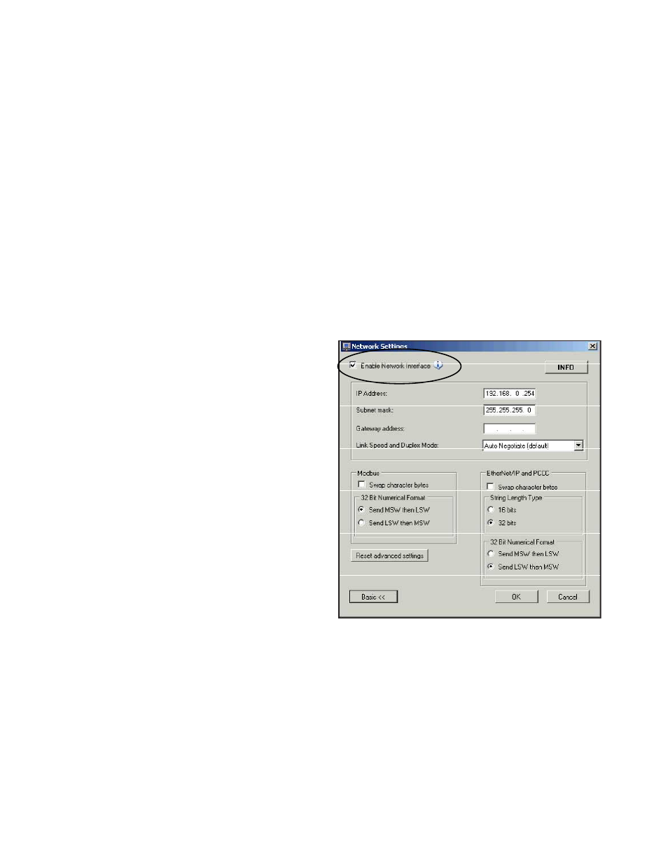
11.1 Ethernet Setting Access
To access the Ethernet settings, click on the Network Settings icon
of the PCI and check the Enable Network Interface box (see figure
below). By default, the Safety Controller communicates using Mod-
bus/TCP and EtherNet/IP.
IP Address. The factory default IP address for the Safety Control-
ler is: 192.168.0.254
Subnet Mask. The factory default Subnet Mask for the Safety
Controller is: 255.255.255.0
Gateway Address. By default, the Safety Controller Gateway Ad-
dress is disabled.
Link Speed and Duplex Mode Options. The following speed and
duplex options are available. The factory default setting is Auto
Negotiate; other options, available by drop-down list, are:
100 Mbps / Full Duplex
100 Mbps / Half Duplex
10 Mbps / Full Duplex
10 Mbps / Half Duplex
Reset Advanced Network Settings. This will cause the advanced
network settings to revert back to the factory default settings.
Ethernet TCP. Default port: 502 (TCP502); Device ID: 1
Figure 70. Ethernet Settings Menu (advanced view shown)
11.2 EtherNet/IP Assembly Objects
Input (T->O) Assembly Objects
The following Instance IDs are supported:
• Instance ID 100 (0x64) with a size (data length) of four 16-bit words. Instance ID 100 is used to access basic information about the
Virtual Status Outputs.
• Instance ID 101 (0x65) with a size (data length) of forty-two 16-bit words. Instance ID 101 is used to access advanced information
(inclusive of the basic information) about the Virtual Status Outputs.
SC22-3/-3E Safety Controller Instruction Manual
124
www.bannerengineering.com - tel: 763-544-3164
P/N 133487 rev. C