1 signals: run and stop states, 2 safety input device properties – Banner SC22-3E Safety Controller with Ethernet User Manual
Page 28
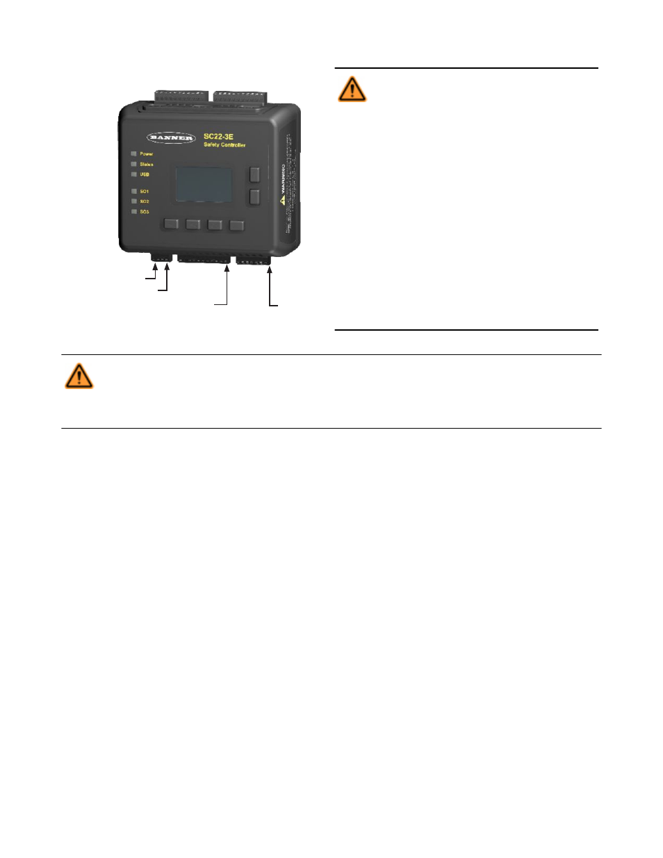
SO1 SO2 SO3
Safety
Outputs
Inputs
S1.............S11
2 x 24V dc (A1)
Inputs
S12...........S22
2 x 0V dc (A2)
0V dc (A2)
O1.........O10
Status
Outputs
System Reset (SR)
Figure 10. Input and output terminal locations
WARNING: . . . Sharing of Safety Inputs
Multiple Safety Controllers must not share safe-
ty input devices; this includes solid-state outputs
from light curtains, Safety Controllers, or other safe-
ty devices. A Safety Output from one Controller can
be connected to a Safety Input of a second Control-
ler. However, the second Controller should be
the only device to which the output from the first
Controller is connected.
If a third device is also connected to the same Safe-
ty Output (now used as the safety input of the sec-
ond Controller): during a power transition of the sec-
ond Controller, the input may be a source of current,
momentarily causing a false ON (Run) signal at the
input of the third device. Failure to connect multi-
ple Controllers correctly could create an unsafe
condition that may lead to serious bodily injury
or death.
WARNING: . . . Failures and Faults
The Safety Controller Safety control can be interfaced with input devices at differing levels of integrity, as described in Appen-
dix A. The user must conduct a Risk Assessment to determine the appropriate level of integration. The user also must
eliminate or minimize the possibility of failures and faults that could result in the loss of the safety function(s).
4.3.1 Signals: Run and Stop States
Dual-channel safety input devices have two separate signal lines. Dual-channel signals for some devices are both positive (+24V dc)
when the device is in the Run state. Others have a complementary circuit structure where one channel is at 24V dc and the other is at 0V
dc when the device is in the Run state. For the sake of clarity, instead of referring to a safety input device as being “ON” (e.g., 24V dc) or
“OFF” (e.g., 0V dc), this manual adopts the Run state/Stop state convention.
4.3.2 Safety Input Device Properties
The Controller can be configured to accommodate many types of safety input devices. However, a number of device properties must be
established (using either the OBI or PCI interface) so that the Controller can properly monitor their signals. These configurable properties
include:
• Device name—This is generated automatically by the Controller and can be changed by the user.
• Circuit type—The circuit and signal convention options that can be selected to define the input device.
• Reset logic—Automatic (Trip mode) or Manual (Latch mode).
• Terminal number—The assignment of input terminals for a device.
• I/O mapping—The logic control relationship between inputs and outputs or between inputs.
• Signal change-of-state—Simultaneous or Concurrent type, and signal convention (high or low)
• Signal debounce time—The signal state transition time.
• Start-up test—An optional precautionary safety input device test required after each power-up.
• Function time limit—The adjustable time limit within which a function is allowed to operate.
• Muteable—Whether or not the device can be muted.
• Bypassable—Whether or not the device can be bypassed.
SC22-3/-3E Safety Controller Instruction Manual
28
www.bannerengineering.com - tel: 763-544-3164
P/N 133487 rev. C